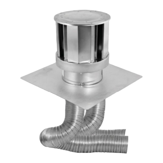
DuraVent DIRECT-TEMP Co-Linear Insert Kit Instrukcja instalacji - Strona 5
Przeglądaj online lub pobierz pdf Instrukcja instalacji dla Wentylator DuraVent DIRECT-TEMP Co-Linear Insert Kit. DuraVent DIRECT-TEMP Co-Linear Insert Kit 16 stron. Selkirk direct vent system

surface damage, caution must be observed
when lowering liner lengths into the masonry
flue.
The top section of the masonry must be water-
tight to prevent moisture from entering the ma-
sonry chimney and causing damage. Consult
the local building authority for more information
on how to seal the damages or unused masonry
section.
Table 1 - Contents of Insert Kits
Part Number
Insert Co-Linear Kit (3"/3")
4DT-33IK35VB
Includes:
2 - 3" x 35' aluminum flex
lengths,
1 - Co-Linear Cap 3"/3",
1 - Hardware pack (screws
and hose clamps),
1 - Installation Instructions.
4DT-34IK35VB
Insert Co-Linear Kit (4"/3")
Includes:
1 - 4" x 35' aluminum flex
length,
1 - 3" x 35' aluminum flex
length,
1 - Co-Linear Cap 4"/3",
1 - Hardware pack (screws
and hose clamps),
1 - Installation instructions.
PLANNING YOUR INSTALLATION:
The DIRECT-TEMP Co-Linear Insert Kit was
designed to be installed in an existing mason-
ry or factory-built chimney, and connected to a
direct vent co-linear gas insert (see Figure 1)
or other appropriate direct vent gas appliance.
It is important to carefully measure the
length of flex needed to reach from the
appliance outlet to the Co-Linear Cap.
If the flex length is too short, a Flex Coupler
(Figure 3) will be needed to attach an addi-
tional length of flex liner. On the exhaust side,
high temperature silicone needs to be applied.
If the flex length is too long, the liner could
sag below the appliance outlet which
could result in a portential fire hazard.
Description
Note: Diagrams & Illustrations Are Not to Scale.
Figure 1
Flex Liner
Sheet Metal
Screws
Hose Clamps
Direct Vent
Co-Linear Gas Insert
Masonry Chimney Installation:
1. Measure the distance between the top of
the masonry chimney and the gas appliance,
allowing for any required bends.
2 . S e l e c t t h e l e n g t h s n e c e s s a r y t o
accommodate the required distance
determined above. Stretch the flexible liners
to the desired lengths (requires 2 people) by
placing both hands around the circumference
of the ends of the liners and gently pulling.
If any flexible liners requires cutting, use a
sharp fine-toothed hacksaw.
3. The exhaust flex length is identified with
red tape at both ends. Use the flex length
with no red tape as the air intake flex length.
If the flex liners are unidentified, mark each
liner at the top and bottom as either exhaust
or intake to prevent confusion later.
4. Insert a rope through the end of the Pull-
Down and tie a knot at the end of the rope.
Attach the Pull-Down to the Flex Liner using
four sheet metal screws as shown (Figure 2).
Carefully feed the liner down the chimney
(Figure 4) one at a time (masonry or factory-
built) and out through the damper.
5
