Apogee SQ-225 Instrukcja obsługi - Strona 11
Przeglądaj online lub pobierz pdf Instrukcja obsługi dla Akcesoria Apogee SQ-225. Apogee SQ-225 16 stron. Quantum sensor

OPERATION AND MEASUREMENT
Connect the sensor to a measurement device (meter, datalogger, controller) capable of measuring and displaying or
recording a voltage signal with a range of 0-2.5 V (SQ-212/222) or 0-5 V (SQ-215/225) to cover the entire range of PPFD from
the sun. In order to maximize the measurement resolution and signal-to-noise ratio, the signal input range of the
measurement device should closely match the output range of the quantum sensors. The amplification circuit requires a
power supply of 2.5-24 VDC (SQ-212/222) or 5-24 VDC (SQ-215/225). NOTE: To prevent sensor damage,
sensor to a power source greater than 24 VDC.
VERY IMPORTANT:
Apogee changed all wiring colors of our bare-lead sensors in March 2018 in conjunction
with the release of inline cable connectors on some sensors. To ensure proper connection to your data device,
please note your serial number or if your sensor has a stainless-steel connector 30 cm from the sensor head then
use the appropriate wiring configuration below.
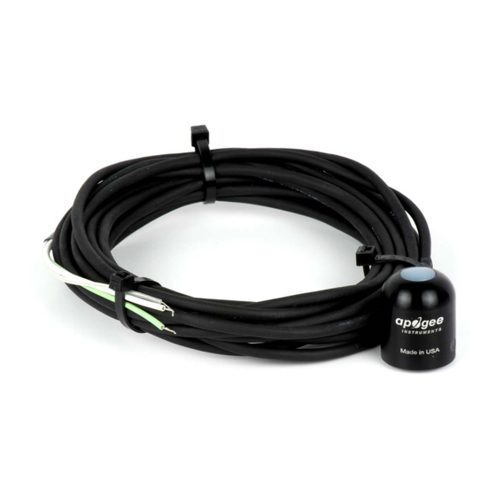
Wiring for SQ-212 and SQ-215 within Serial Number range 0-7597
Wiring for SQ-212 and SQ-215 with Serial Numbers 7598 and above or with a cable connector
DO NOT connect the
Green: Positive (signal from sensor)
White: Input power
Clear: Ground (from sensor signal and input
power)
Black: Ground (from sensor signal and output power)
Red: Input Power SQ-212 3.3-24 V DC,
SQ-215 5.5-24 V DC
White: Positive (signal from sensor)
Clear: Shield/Ground
11
