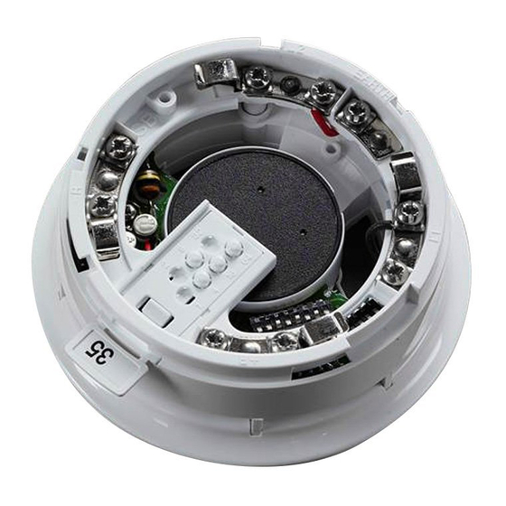
Apollo 45681-276 Instrukcja instalacji - Strona 2
Przeglądaj online lub pobierz pdf Instrukcja instalacji dla Wyposażenie morskie Apollo 45681-276. Apollo 45681-276 2 stron. Ancillary base sounder

Mounting Instructions
The Ancillary Base Sounder may be secured to a UK standard conduit box or surface mounted (providing
there is access through the surface for cabling).
Wiring details
Note: The sounder is polarity sensitive (supply reversal protected) and will not function if it has been
wired incorrectly.
Connect the positive and negative XP95/Discovery loop cables to the L2 and L1 terminals respectively,
observing polarity. The wiring terminals accept solid or stranded cables up to 2.5mm². Functional earth
or screen cables may be terminated to the EARTH connection.
XPERT card
Loop negative (-)
L1
Cable entry
Wiring diagram—Ancillary Base Sounder
Maximum Loop Current Consumption at 24V
Quiescent
Operated 85dB(A)
The maximum number of Ancillary Base Sounders with detectors permitted between standard XP95
isolators is 20. If this limit is exceeded, short-circuit isolators may trip and a fault will be reported at the
control panel.
Volume control
No fi eld wires are
connected to this
terminal
Loop positive (+)
EARTH
L2
Earth (screen)
continuity terminal
<100μA
3.2mA
Address Setting
The address of the base sounder is set by means of the XPERT card. A complete diagram of address
settings is shown below.
XPERT card addressing
Select the desired address and remove the pips indicated in black. Remove pips with a screwdriver.
1
2
3
4
5
6
7
1
2
3
4
5
6
7
16
17
18
19
20
21
22
16
17
18
19
20
21
22
31
32
33
34
35
36
37
31
32
33
34
35
36
37
46
47
48
49
50
51
52
46
47
48
49
50
51
52
61
62
63
64
65
66
67
61
62
63
64
65
66
67
76
77
78
79
80
81
82
76
77
78
79
80
81
82
91
92
93
94
95
96
97
91
92
93
94
95
96
97
106
107
108
109
110
111
112
106
107
108
109
110
111
112
121
122
123
124
125
126
121
122
123
124
125
126
Commissioning
It is important that the Ancillary Base Sounder be fully tested after installation. A Test Set, part no.
55000-870, may be used to carry out func tion al testing of individual units. The test set can also perform
data integrity tests of an entire system.
Volume Control
The volume control can be used to reduce the sound steplessly from 85dB(A) to 70
8
9
10
11
12
13
14
8
9
10
11
12
13
14
23
24
25
26
27
28
29
23
24
25
26
27
28
29
38
39
40
41
42
43
44
38
39
40
41
42
43
44
53
54
55
56
57
58
59
53
54
55
56
57
58
59
68
69
70
71
72
73
74
68
69
70
71
72
73
74
83
84
85
86
87
88
89
83
84
85
86
87
88
89
98
99
100
101
102
103
104
98
99
100
101
102
103
104
113
114
115
116
117
118
119
113
114
115
116
117
118
119
±
5dB(A).
15
15
30
30
45
45
60
60
75
75
90
90
105
105
120
120
