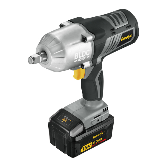
DUROFIX RI2036A3 Podręcznik z informacjami o produkcie - Strona 11
Przeglądaj online lub pobierz pdf Podręcznik z informacjami o produkcie dla Sterownik udarowy DUROFIX RI2036A3. DUROFIX RI2036A3 16 stron. Brushless impact wrench

2.
Make sure the socket is fixed in the anvil while clicking on the ball of the anvil.
REMOVING SOCKETS
Always follow the procedure below to remove a socket.
CAUTION
FUNCTIONS & DISPLAY:
1.
There are 4 stages of battery capacity gauge on LCD.
2.
When pressing VSR switch, then the illuminative LED will be on at the same time.
There are 28 stages of torque clutches and one "MAX" stage.
3.
REFERENCE TORQUE VALUES OF EACH TORQUE CLUTCH STAGE
Stage 1: average value: (45 ft-lbs) 60 Nm
Stage 2: average value: (60 ft-lbs) 80 Nm
Stage 3: average value: (75 ft-lbs) 100 Nm
Stage 4: average value: (90 ft-lbs) 120 Nm
Stage 5: average value: (105 ft-lbs) 140 Nm
Stage 6: average value: (120 ft-lbs) 160 Nm
..........
Stage 27: average value: (435 ft-lbs) 580 Nm
Stage 28: average value: (450 ft-lbs) 600 Nm
Max. Torque value: (590 ft-lbs) 800 Nm
NOTE
Please note these values are lab. test value for reference only. Accuracy varies
due to bolt size, grade, and various other factors.
LED INDICATING LAMP SIGNAL & MESSAGE ON LCD DURING
OPERATION:
1.
During Operation: LCD will show the setting stage of digital clutch.
2.
Designated Torque Reached: LED indicating lamp will stay on in green and LCD
will show the setting stage of digital clutch.
3.
When the battery voltage is under 14.5 V, the power will be cut-off. At the same
time, LED indicating lamp will be on in red and LCD panel will show "LV".
4.
When the battery temperature is over 154.4°F (70°C), the power will be cut-off. At
the same time, LED indicating lamp will be on in red and LCD panel will show
"OH".
Always set switch (5) to off position when installing and
removing socket.
OPERATION
-10
