Datakom DKM-407 Podręcznik - Strona 3
Przeglądaj online lub pobierz pdf Podręcznik dla Przyrządy pomiarowe Datakom DKM-407. Datakom DKM-407 4 stron. Din rail type network analyzer
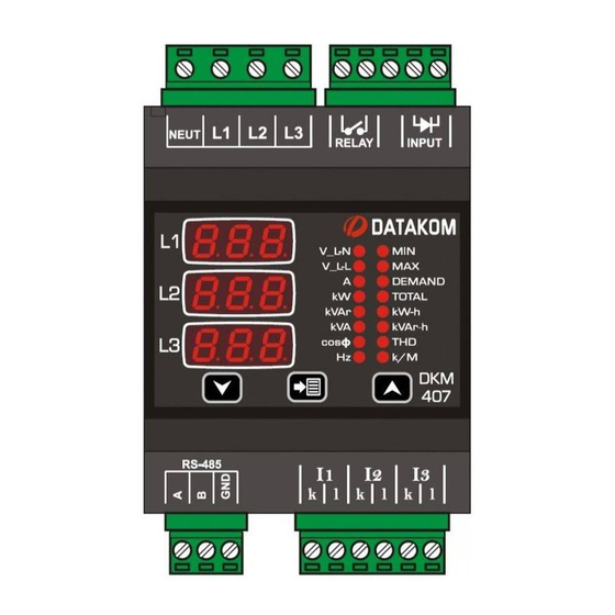
PUSHBUTTON FUNCTIONS
Three buttons on the front panel provide
access to configuration and measurement
screens.
BUTTON
FUNCTION
Selects display context
THD display
Minimum values display
Maximum values display
Demand display
HELD PRESSED FOR 5SEC:
resets min-max values and
displays minimum phase-to-
neutral voltages.
IF NO BUTTON PRESSED
FOR 5 MINUTES:
returns to the main display
screen
PROGRAMMING
BUTTON
FUNCTION
In order to enter the
configuration menu,
hold both arrow buttons
pressed for 2 seconds.
Pressing the SET button will
save the current parameter
and display the next
parameter.
Holding the SET button
pressed for 2 seconds will
display the previous
parameter.
Upper screen
Increase (config.)
Lower screen
Decrease (config.)
PROGRAM PARAMETERS
SCREEN
FUNCTION
0: No action
1: Reset Demand values
0: No action
1: Reset kWh and kVArh
counters
0: No action
1: Reset hour counter
0: No action
1: Reset alarms
Default screen selection (refer user
manual)
Current transformer primary (xxx/5A
format)
Voltage transformer ratio
(xxx.x/1 format)
High voltage alarm limit. If set to 0
then does not check high voltage.
Low voltage alarm limit. If set to 0
then does not check low voltage.
High frequency alarm limit. If set to 0
then does not check high frequency.
Low frequency alarm limit. If set to 0
then does not check low frequency.
Overcurrent alarm limit. If set to 0
then does not check the limit.
High active power alarm limit. If set
to 0 then does not check the limit.
Low active power alarm limit. If set
to 0 then does not check the limit.
High reactive power alarm limit. If
set to 0 then does not check the
limit.
Low reactive power alarm limit. If set
to 0 then does not check the limit.
High power factor alarm limit. If set
to 0 then does not check the limit.
Low power factor alarm limit. If set
to 0 then does not check the limit.
Device Modbus address (0-255)
RS-485 baud rate
(0=2400 / 1=4800 / 2=9600 /
3=19200 / 4=38400 / 5=57600 /
6=115200)