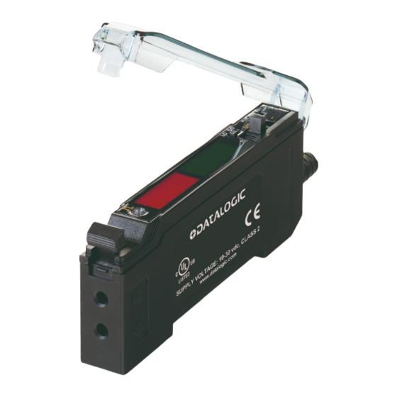
Datalogic S70-5-E3-PI Skrócona instrukcja obsługi - Strona 6
Przeglądaj online lub pobierz pdf Skrócona instrukcja obsługi dla Akcesoria Datalogic S70-5-E3-PI. Datalogic S70-5-E3-PI 10 stron. Analogue output

ADJUST MODE
Sliding the RUN/PRG/ADJ mode switch to the ADJ position allows the user to perform Expert TEACH/SET methods and Manual Adjustment
of the threshold and the midpoint or endpoints of the analogue output depending on whether a 1-point SET or 2-point TEACH was used.
NOTE: For threshold and analogue endpoints, when teaching CH2, the gain setting will be the same as the gain setting made during
the CH1 teach. Reteaching CH1 may invalidate the previous CH2 teach.
TEACH Procedures
The instruction manual has detailed instructions for these TEACH modes:
CH1 Analogue Output
- Two-Point TEACH
•
Establishes defined endpoints for the analogue output range
•
Analogue endpoints can be adjusted by using the "+" and "-" Navigation key (Manual Adjust)
Two-Point TEACH is used when two conditions can be presented statically to the sensor. The first taught condition is set to 1 V (4 mA), and
the second taught condition to 5 V (20 mA). The order of the taught points determines the slope. If the first taught condition is darker, the
slope will be positive. If the first taught condition is lighter, the slope will be negative. Reverse the slope of the analog output by changing the
AOut SLPE menu setting.
NOTE: Depending on the application configuration and fibers used, the analogue function may or may not behave linearly.
The received light intensity will be dictated by the inverse square properties of light.
- One-Point SET
•
Defines the 3 V (12 mA) midpoint of the analogue output
•
Analogue midpoint can be adjusted by using the "+" and "-" Navigation key (Manual Adjust)
A single sensing condition is presented, and the sensor positions the midpoint of its analogue range (3 V or 12 mA) exactly at the presented
condition. The size of the window is determined by the OFSt Pct1 menu setting. The slope of the analogue output is determined by the AOut
SLPE setting.
CH1 Analogue
Two-Point TEACH
One-Point SET
Current-Sourcing
Models
20 mA
4 mA
Two-Point TEACH (Light Operate shown)
Current-Sourcing
Models
20 mA
12 mA
4 mA
- OFSt Pct1
One-Point SET (Light Operate shown)
CH2 Discrete
Two-Point TEACH
Dynamic TEACH
Window SET
Light SET
Dark SET
Calibration SET
Voltage-Sourcing
Models
5 VDC
LO
Slope
DO
Slope
1 VDC
Voltage-Sourcing
Models
LO
5 VDC
Slope
3 VDC
Single
PointTau
ght
DO
Slope
1 VDC
+ OFSt Pct1
Signal
6
