4x4 Traction BeadLocker Instrukcja instalacji - Strona 5
Przeglądaj online lub pobierz pdf Instrukcja instalacji dla Akcesoria samochodowe 4x4 Traction BeadLocker. 4x4 Traction BeadLocker 8 stron. Internal beadlock

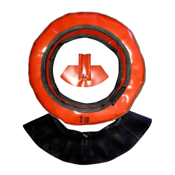
1) First, ensuring that all beadlock components are well
lubricated with the powder before you start, mount
the casing's inside bead on the rim.
2) Roughly position the stitched overlap in the beadlock
casing 180° across from the valve stem holes.
3) Now, gently force the tube over the rim so it nests
within the casing. Put the tube valve stem through
the newly drilled hole, install the O-Ring and washer,
snug the tube up against the rim, then finger tighten
the nut. (To be fully fastened later)
4) Remove the tube valve core and slightly inflate the
tube to ensure it is not twisted. Deflate the tube.
5) Next, pull the casing's outside bead over the rim.
CAREFULLY POSITION THE BEADLOCK & TUBE!
This is the important part of the installation. You must
ensure that both the inside and outside beadlock beads are
properly positioned and the tube is neither pinched nor in a
position that it will become pinched when fully inflated.
Since you cannot see the inside bead, use your fingers to
feel inside the tire.
1) The objective is to ensure that the tube is not outside
either the bead lock casing, or the tire as shown in A.
2) The beadlock beads must be properly positioned as
shown in B. The beadlock beads must not be folded
up against the beadlock sidewall in either direction as
shown in C and D.
3) To make the beadlock mounting process easier,
gently inflate the tube to 0.1 to 0.15 bar and
position.
4) Finally, take your time and feel 100% of both the
inside and outside beadlock beads to ensure that
they are positioned as shown in B and that the tube is
centrally located and is not pinched, trapped outside
the casing, or in a position to become trapped.
5) Once you are satisfied that the beadlock assembly is
properly positioned, deflate the tube to "limp." Give it
a little body, but not so much as to interfere with
mounting the outside tire bead, which may force a
fully inflated tube outside the casing in an unseen
area within the tire. That will undesirably pinch the
tube!
6) You are now ready to fit the special air channel.
!
CAREFULLY POSITION
THE BEAD LOCK & TUBE !
This is the step that makes your
installation perfect. You must
ensure that both the Inside and
Outside bead lock Beads are
properly positioned and the
tube is neither pinched nor in a
position that it will become
pinched when fully inflated.
Since you cannot see the
inside Bead, think like a rac-
coon. Patiently use your fingers
to "take a look." Your objective
is to ensure that the Air Channel
Walls and Floor are under the
tube, and that the tube is not
outside either the bead lock Cap
or the tire as shown in A. This is
most likely to occur on the out-
side of the rim since the rim
Well is very close to the rim's
bead bump making a large gap
possible. The bead lock Beads
must be properly positioned as
shown in B.
The bead lock
Beads must not be folded up
against the bead lock Sidewall
in either direction as shown in C
and D.
To make the be ad lock
mounting process easier, gently
inflate the tube to 1 or 2 PSI (7
to 14kPa) and position the Air
Channel so it is centered on the
new valve stem remembering
that the replacement valve stem
notch must point at the Air
Channel Walls. Finally, with your
hand, patiently, carefully and
meticulously feel 100% of both
the Inside and Outside bead
lock Beads to ensure that they
are positioned as shown in B
and that the tube is centrally
located and is not pinched,
trapped outside the CAP or in a
position to become trapped.
5
5!
