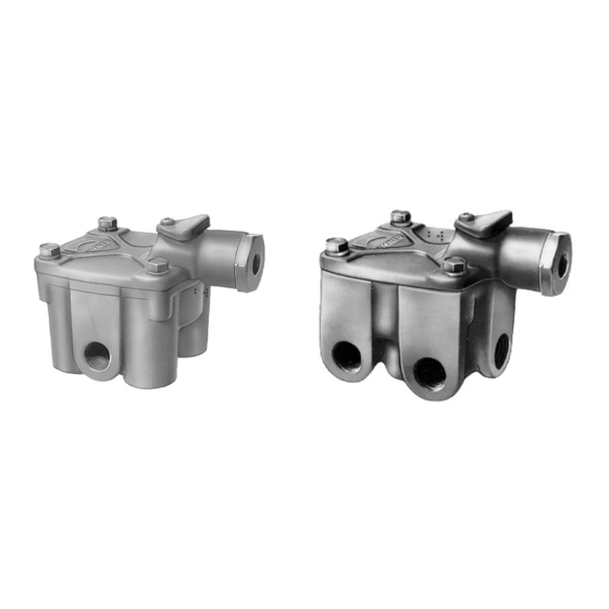
BENDIX R-14V Podręcznik - Strona 3
Przeglądaj online lub pobierz pdf Podręcznik dla Jednostka sterująca BENDIX R-14V. BENDIX R-14V 6 stron. Universal service replacement relay valves kit
Również dla BENDIX R-14V: Instrukcja instalacji (6 strony)

No two vehicles operate under identical conditions, as a
result, maintenance intervals may vary. Experience is a
valuable guide in determining the best maintenance interval
for air brake system components. At a minimum, the valve
should be inspected every 6 months or 1500 operating hours,
whichever comes first, for proper operation. Should the valve
not meet the elements of the operational tests noted in this
document, further investigation and service of the valve may
be required.
OPERATIONAL AND LEAKAGE TEST
1. Chock the wheels, fully charge the air brake system
and adjust the brakes.
2. Make several brake applications and check for prompt
application and release at each wheel.
3. Check for inlet valve and o-ring leakage.
A. Make this check with the service brakes released
™
when the R-12
or R-14
service brakes.
B. Make the check with the spring brakes applied
(PARK) when the R-14
spring brakes. Coat the exhaust port and the area
around the retaining ring with a soap solution; a 1"
bubble in 3 seconds leakage is permitted.
4. Check for exhaust valve leakage.
A. Make this check with the service brakes fully applied
™
if the R-12
or R-14
B. Make this check with the spring brakes fully released
™
if the R-14
valve is used to control the spring brakes.
Coat the exhaust port with a soap solution; a 1" bubble
in 3 seconds leakage is permitted. Coat the outside
of the valve where the cover joins the body to check
for seal ring leakage; no leakage is permitted.
5. If the R-14
™
valve is used to control the spring brakes,
place the park control in the released position and coat
the balance port with a soap solution to check the
diaphragm and its seat. Leakage equivalent to a 1" bubble
in 3 seconds is permitted.
Note: If the anti-compound feature is in use, the line attached
to the balance port must be disconnected to perform this
test.
If the valves do not function as described above, or if leakage
is excessive, it is recommended that the valves be replaced
with new or remanufactured units or repaired with genuine
Bendix parts, available at any authorized Bendix parts outlet.
REMOVAL AND INSTALLATION
REMOVAL
1. Block and hold vehicle by means other than air brakes.
2. Drain air brake system reservoirs.
3. If entire valve is to be removed, identify air lines to facilitate
installation.
4. Disconnect air lines from valve* .
™
valve is used to control the
™
valve is used to control the
™
valve control the service brakes.
5. Remove valve from reservoir or if remotely mounted,
remove mounting bolts and then valve.
*It is generally not necessary to remove entire valve to service
the inlet/exhaust valve. The inlet/exhaust valve insert can be
removed by removing the snap ring, exhaust cover assembly
and then inlet/exhaust valve.
Caution: Drain all reservoirs before attempting to remove
the inlet exhaust valve.
DISASSEMBLY
Note: Prior to disassembly, mark the location of the
mounting bracket to the cover and the cover to the body.
1. Remove the four (4) cap screws and lockwashers
securing the cover to the body.
2. Remove the cover, sealing ring, and mounting bracket.
3. Remove the piston and o-ring from the body.
4. While depressing the exhaust cover, remove the retaining
ring and slowly relax the spring beneath the exhaust
cover.
5. Remove the exhaust cover assembly and o-rings.
6. Remove the inlet/exhaust valve return spring from the
body.
7. Remove the inlet/exhaust valve from the body.
8. Remove the valve retainer from the inlet/exhaust valve.
9. Remove the Phillips head screw and exhaust cover from
the R-14
™
valve cover.
10. Remove the service port cap nut and o-ring from the
™
R-14
valve.
11. Remove the diaphragm from the R-14
CLEANING AND INSPECTION
1. Wash all metal parts in mineral spirits and dry them
thoroughly.
(Note: When rebuilding, all springs and all rubber parts
should be replaced.)
2. Inspect all metal parts for deterioration and wear, as
evidenced by scratches, scoring and corrosion.
3. Inspect the exhaust valve seat on the relay piston for
nicks and scratches which could cause excessive
leakage.
4. Inspect the inlet valve seat in the body for scratches and
nicks, which could cause excessive leakage.
5. Inspect the exhaust seat of the quick release diaphragm
™
in the R-14
valve cover and make sure all internal air
passages in this area are open and clean and free of
nicks and scratches.
6. Replace all parts not considered serviceable during these
inspections and all springs and rubber parts. Use only
genuine Bendix replacement parts, available from any
authorized Bendix parts outlet.
™
valve cover.
3
