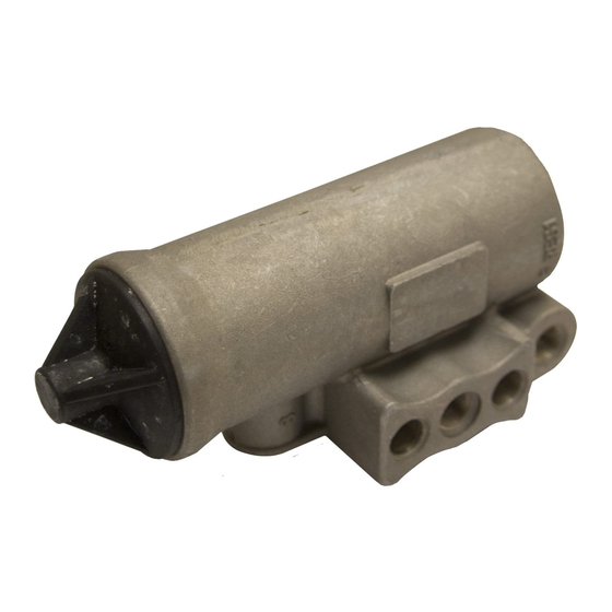
BENDIX D-2 GOVERNOR Podręcznik - Strona 4
Przeglądaj online lub pobierz pdf Podręcznik dla Części samochodowe BENDIX D-2 GOVERNOR. BENDIX D-2 GOVERNOR 4 stron. Governor

CLEANING AND INSPECTION
1. Clean all remaining parts in mineral spirits.
2. Inspect body for cracks or other damage. Be particu-
larly careful that all air passages in the body, exhaust
stem, and piston are not obstructed.
3. Check springs for cracks, distortion, or corrosion.
4. Replace all parts which are worn or damaged.
ASSEMBLY
Prior to assembly, lubricate the two lower body bores, all
o-rings and o-ring grooves with lubricant provided. Note: Also
spring guide and adjusting screw (if disassembled).
1. Install o-ring (12) in piston (11). Replace washer (13)
and retaining ring (14) on nonmetallic piston if removed
during disassembly.
2. Drop the inlet/exhaust valve (10) into place at the
bottom of the piston (11).
3. Nonmetallic Piston: Install the inlet/exhaust valve spring
(9) with the small end against the valve, place the retain-
ing ring (15) on top of the large end of the valve spring (9)
[concave side of retaining ring (15) facing away from pis-
ton (11)], press into piston with thumb, making sure ears
of retaining ring (15) are seated into piston (11) as far as
possible.
Note: Do not use a press or hammer to install retaining
ring. Excessive force may damage the piston.
Metallic Piston: Install the inlet/exhaust valve spring
(9) with the small end against the valve. Press the spring
down until the larger coiled end snaps into the recess
inside the piston (11).
4. Install the piston o-rings (8) on the piston (11).
5. Install the exhaust stem spring (6) in the piston (11) with
the large coil end next to the piston.
6. Install the exhaust stem (5) through spring (6) and into
piston (11).
7. Install assembled piston (11) into the governor body (2).
8. If the spring assembly was not disassembled, proceed
to Step 9. If the spring assembly was disassembled,
the following instructions apply: install on the adjusting
screw (4) in this order; lower spring seat (19), spring
guide (18), spring seat (19), pressure setting spring (17),
hex-shaped upper spring seat (16). Screw the upper
spring seat onto the adjusting screw until the distance
from the top of the seat to the bottom of the adjusting
screw head is approximately 1-7/8 inches. Install the
lock nut (3).
4
BW1425 © 2004 Bendix Commercial Vehicle Systems LLC. All rights reserved. 3/2004 Printed in U.S.A.
9. Install the adjusting screw (4) and spring assembly into
the governor body (2).
10. Install retaining ring (1) making certain that it seats com-
pletely into the groove in the governor body (2).
If cover provided in kit is black rubber, (refer to Figure 2)
install by pushing it onto the adjusting screw.
If cover provided in kit is clear nonmetallic, install o-ring
(20) and screw cover onto the adjusting screw. Tighten
until cover bottoms on governor body. Note: O-ring (20)
is used only on Hi-Temp and waterproof governors. If
cover provided in kit is blue nonmetallic place cover over
one edge of top of governor; with index finger catch knob
on top of cover and pull until cover snaps into place.
Note: Nonmetallic cover should be at room temperature
for ease of assembly. Do not attempt to force cover on
square to the governor body.
11. Install filters (7) in governor body. The head of a pencil
makes a satisfactory installation tool.
INSTALLATION
1. If the governor is compressor-mounted, clean the mount-
ing pad on both the compressor and governor. Clean
connecting line, or lines. Be certain the unloading port
is clear and clean. If the governor is mounted remotely,
it should be positioned so that its exhaust port points
down. It should be mounted higher than the compressor
so that its connecting lines will drain away from the
governor.
2. Install governor.
3. If compressor-mounted type, use the governor mounting
gasket provided.
4. Connect air lines to governor.
5. Perform operating and leakage tests as outlined under
Service Tests section.
