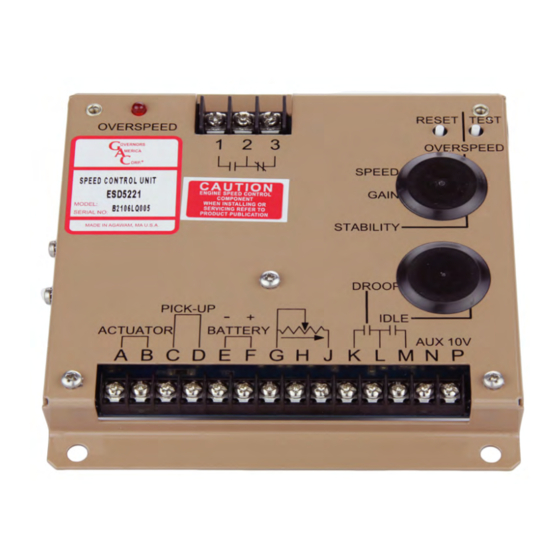
GAC ESD5200 Series Podręcznik - Strona 6
Przeglądaj online lub pobierz pdf Podręcznik dla Jednostka sterująca GAC ESD5200 Series. GAC ESD5200 Series 7 stron. Speed control unit

9
ADDITIONAl FEATURES & OPTIONAl WIRINg (CONTINUED)
wIDe ranGe remoTe varIaBLe SPeeD oPeraTIon
A single remote speed adjustment potentiometer can be used to adjust the
engine speed continuously over a specific speed range.
Select the desired speed range and corresponding potentiometer value as
shown in Speed Range table. If the exact range cannot be found, select the
next higher range potentiometer.
An additional fixed resistor may be placed across the potentiometer to obtain
the exact desired range. Connect the speed range potentiometer as shown in
section 4, Wiring.
To maintain engine stability at the minimum speed setting, a small amount of
droop can be added using the DROOP adjustment. At the maximum speed
setting the governor performance will be near isochronous, regardless of the
droop adjustment setting.
Contact GAC for assistance if difficulty is experienced in obtaining the de-
sired variable speed governing performance.
10
SYSTEM TROUBlESHOOTINg
InSUffIcIenT maGneTIc SPeeD SIGnaL
A speed sensor signal of 3 volts RMS or greater at governed speed is recommended. Measurement of the signal is made at Terminals
C and D.
A strong magnetic speed sensor signal eliminates the possibility of missed or extra pulses. The speed control unit governs well with 0.5
volts RMS speed sensor signal.
The amplitude of the speed sensor signal can be raised by reducing the gap between the speed sensor tip and the engine ring gear. The
gap should not be any smaller than 0.020 in [0.5 mm]. When the engine is stopped, back the speed sensor out by 3/4 turn after touching
the ring gear tooth to achieve a satisfactory air gap.
SYSTem InoPeraTIve
If the engine governing system does not function, the fault may be determined by performing the voltage tests described in Steps 1
through 4. Positive (+) and negative (-) refer to meter polarity. Should normal values be indicated during troubleshooting steps, and then
the fault may be with the actuator or the wiring to the actuator. Tests are performed with battery power on and the engine off, except where
noted. See your actuator publication for troubleshooting and testing.
STeP
wIreS
cHecK
1
F(+) & E(-)
Battery Supply
Voltage
(12 or 24 V DC)
2
C(+) & D(-)
1.0 V AC RMS
minimum while
cranking
3
P(+) & G(-)
10 V DC, Internal
Supply
4
F(+) & A(-)
1.0 - 2.0 V DC while
cranking
1.
DC battery power not connected. Check for blown fuse.
2.
Low battery voltage
3.
Wiring error
1.
Gap between speed sensor and gear teeth too great. Check Gap.
2.
Improper or defective wiring to the speed sensor. Resistance between D and C should be 160 to
1200 Ω. See specific mag pickup data for resistance.
3.
Defective speed sensor.
1.
Short on Terminal P.
2.
Defective speed control unit.
1.
SPEED parameter set too low
2.
Short/open in actuator wiring
3.
Defective speed control
4.
Defective actuator, see your actuator's Troubleshooting guide.
6
SPeeD ranGe
PoTenTIomeTer
900 Hz
540 RPM
2400 Hz
1440 RPM
3000 Hz
1800 RPM
3500 Hz
2100 RPM
3700 Hz
2220 RPM
RPM values shown are for 100 teeth
noTe
flywheel
conversion formulas:
Hertz
= (RPM x #Teeth)
MAG PICKUP
60
RPM = (Hertz
x 60)
MAG PICKUP
#Teeth
ProBaBLe caUSe
ESD5200 Series Speed Control Unit 1-2021-C3 PIB1030
Governors America Corp. © 2021 Copyright All Rights Reserved
vaLUe
1 kΩ
5 kΩ
10 kΩ
25 kΩ
50 kΩ
