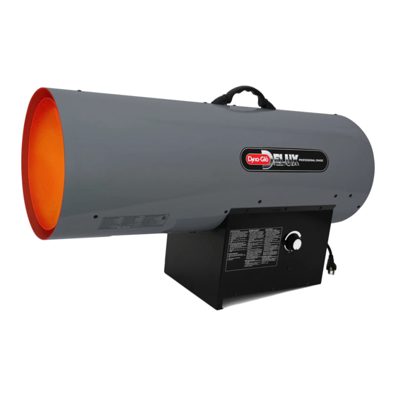
Dyna-Glo Delux RMC-FA300DGD Instrukcja obsługi i instrukcja części - Strona 3
Przeglądaj online lub pobierz pdf Instrukcja obsługi i instrukcja części dla Grzałka Dyna-Glo Delux RMC-FA300DGD. Dyna-Glo Delux RMC-FA300DGD 12 stron. Delux propane construction heater
Również dla Dyna-Glo Delux RMC-FA300DGD: Instrukcja obsługi i instrukcja części (11 strony)

Dyna-Glo
Delux Operating Instructions and Parts Manual
TM
Models RMC-FA300DGD
• Gas supply connections should be
checked using a 50/50 solution of liquid
dish soap and never use a flame to
check for gas leaks.
• The electrical connection & grounding
must comply with National Electrical
Code. ANSI/NFPA 70 or in Canada CSA
C22.1, Canadian Electrical Code, Part 1.
Use only a properly grounded three (3)
prong receptacle.
• Do not restrict inlet or outlet by any
means. The flow of combustion and
ventilation air is not to be obstructed.
• This heater should not be directed
toward any propane-gas container
within 20 ft (6 m). The heater must be
located at least 6 ft. (1.83 m) in the U.S.;
or (ii) 10 ft. (3 m) in Canada, from any
propane gas container.
• The propane cylinder supply system
must be arranged to provide for vapour
withdrawal from the operating cylinder.
• This heater is not to be used with
external thermostats, timers or other
devices that control or alter electrical
supply to the heater.
Clean Heated
Air Out (Front)
Combustion Chamber
Air For Heating
Figure 2 – Cross Section Operational View
For Technical Support or Troubleshooting, Call: 1-877-447-4768, 8:30 am - 4:30 pm CST
WARNING
during operation and at shutdown, in order
to prevent a flame-out condition which
could result in personal injury or property
damage.
• Do not adjust regulator below 7 PSIG
or above 10 PSIG
Theory of Operation
FUEL SYSTEM
The hose/regulator assembly runs from
the propane supply to the heater itself.
After the gas runs through the hose
and regulator, it passes through the
solenoid valve and out the nozzle into
the combustion chamber.
AIR SYSTEM
The internal motor turns the fan, which
pushes air around and through the
combustion chamber. Here the air is
heated and provides a constant stream
of warmth.
IGNITION SYSTEM
The spark module sends voltage to the
ignitor. The ignitor ignites the fuel and
air mixture.
Ignitor
Fan
Nozzle Solenoid Valve
PCB Control
Spark Module (Spark Ignitor)
Air For Combustion
Motor and fan must be
running before lighting,
Motor
Cool Air In (Back)
On/Off Switch
Power Cord
Hose / Regulator
Assembly
3
NEVER LEAVE THE HEATER
UNATTENDED WHILE BURNING!
SAFETY CONTROL SYSTEM
This system shuts the heater down
if the flame is extinguished. The fan
and motor will continue to operate,
butthere will not be any heat.
PROPANE SUPPLY
All propane gas and tanks are to be
provided by the user.
This heater should only be used with
a tank that has a vapor withdrawal
system. Refer to the Standard of
Storage and Handling of Liquefied
Petroleum Gas, ANSI/NFPA 58, Chapter
5. Your local fire department or library
will have this information.
Two factors will dictate how much
propane is used from each tank:
1. The amount of gas in each tank.
2. The surrounding air temperature at
each tank.
The chart below shows how many tanks
should be used at a given tempera ture.
This heater should not be operated with
a tank smaller than 100 pounds.
As the tempera ture drops, less gas is
Average
Temperature
at Tank Location
°F
40
°C
32
Use larger tank
40
4.44
20
Use larger tank
32
0
10
Use larger tank
20
-6.67
0
Use larger tank
10
-12.22
-10
Use larger tank
0
-17.78
-20
Use larger tank
-10
-23.33
Use larger tank
-20
-28.89
vaporized, so a larger tank may be
necessary in very cold weather. Never
operate this heater with a tank smaller
than 100 pounds. Your local propane
dealer can help you select the proper
tank size and configuration.
www.ghpgroupinc.com
Number
of Tanks
3
