Gage Bilt GB715 Instrukcja instalacji - Strona 10
Przeglądaj online lub pobierz pdf Instrukcja instalacji dla Narzędzia do nitów Gage Bilt GB715. Gage Bilt GB715 17 stron.
Również dla Gage Bilt GB715: Oryginalna instrukcja obsługi (20 strony)
WARNING:
Do not cycle tool without air bleeder assy (704153), or the screw and stat-o-seal, installed in tool head. Severe personal injury could result.
CAUTION:
Before filling handle assy , air piston assy should be all the way down.
CAUTION:
When forcing piston rod assy (704138) downward, with head cylinder assy (703124) removed, hydraulic oil will eject forcibly
from handle assy (704132).
CAUTION:
When bleeding tool, ensure tubing is free from kinks or other obstructions.
CAUTION:
Use CAUTION when removing screws, air bleeder assy (704153) and fill bottle (745263). Hydraulic oil may be under pressure.
Note:
Air Bleeder Assy (704153) is required.
To replace a small amount of oil follow BLEEDING steps 4-7.
Should it become necessary to completely refill the tool (as would be required after tool has been dismantled and reassembled), take
the following steps.
1. Remove head cylinder assy (715110) from handle assy (704132). Slowly push piston (715107) completely forward.
2. Fill the oil passage on top of handle assy (704132) with automatic transmission oil, Dexron III or equivalent. When looking at the
top of the handle assy (704132), the oil passage is the hole that is counterbored for o'ring (S832).
3. Replace head cylinder assy (715110) with care, insuring gasket (704129) and o'ring (S832) are properly installed. Torque button
head cap screws (A-928) uniformly to 40 inch lbs. to prevent leakage around gasket (704129).
4. Ensure tool is disconnected from air source. Remove button head cap screw (402482) and stat-o-seal (S572) from head cylinder
assy (715110).
5. Install air bleeder assy (704153) and connect tool to air line. Cycle ten times to fully circulate oil through hydraulic system.
6.
DISCONNECT AIR FROM
on head cylinder assy (715110) and torque to 35-40 inch lbs. Reconnect air and cycle tool five more times.
7. Check tool stroke of 1.200" min. (30.5 mm). We recommend using dial calipers. With the actuator lever assy released (704343),
check dimension (A). While holding actuator lever assy (704343) in, check dimension (B). Add dimension (B) to dimension (A). If
stroke is not consistent within 1/64" (.0156) repeat bleeding steps 4-7.
Bleeder hole on head cylinder (715110)
Button head cap screw (402482)
& stat-o-seal (S572)
GB715 S/N: 1242 AND ABOVE
PLEASE CONTACT GAGE BILT FOR ALL OTHER SERIAL NUMBERS.
FILLING AND BLEEDING
TOOL. Remove air bleeder assy (704153). Install button head cap screw (402482) and stat-o-seal (S572)
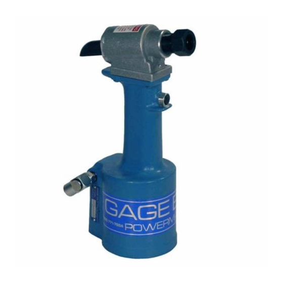
Image may not reflect actual
Air Bleeder Assy (704153)
10
REV. 2/16