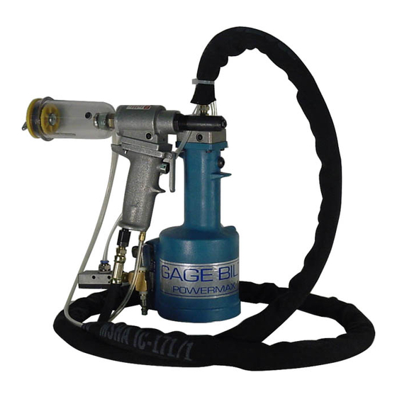
Gage Bilt GB734SHV Podręcznik - Strona 6
Przeglądaj online lub pobierz pdf Podręcznik dla Narzędzia do nitów Gage Bilt GB734SHV. Gage Bilt GB734SHV 13 stron. Installation tool
TROUBLESHOOTING
Providing all maintenance conditions have been met, follow this systematic approach to diagnosis.
1. MORE THAN ONE PULL IS REQUIRED TO BREAK RIVET.
a) Tool needs to be bled. (See filling and bleeding instructions.)
b) Spring has fatigued, replace.
c) Jaws are stripped or packed with chips. Clean or replace.
d) Incorrect nose tip.
2. SLOW OR PARTIAL OPERATION WHEN THE ACTUATOR LEVER ASSY (704312) IS DEPRESSED
a) O'ring (A-289) and Back-up Ring (401112) on piston (734107) could be worn or damaged. Replace.
b) Back-up Ring (S908) and O'ring (A-201) on piston rod assy (744136) could be worn or damaged. Replace.
c) Muffler (744143) or filter inside valve spool assy (743142) may be plugged with dirt. Clean thoroughly and back-blow with
compressed air.
d) Hole in metering screw in valve spool assy (743142) may be blocked or damaged. Hole diameter should be .028". Clear
and size or replace.
3. NO OPERATION WHEN ACTUATOR LEVER ASSY (704312) IS DEPRESSED
a) Tool seized due to mechanical failure or damaged parts.
4. OIL LEAKAGE
a)
DO NOT
OPERATE WITH OIL LEAKING FROM TOOL. HIGH PRESSURE OIL MAY CAUSE SEVERE PERSONAL INJURY.
b) Any oil leaking externally should be traced to its source. An o'ring or seal that leaks should be replaced.
5. AIR BYPASS FROM VALVE HOUSING
a) If the spring (744144) breaks or dislodges, air will flow freely through the muffler (744143). Replace or reset. Valve spring
installation tool (744151) is recommended.
b) Check o'rings on valve sleeve (743144), valve spool assy (743142), and valve plug (744142). If worn or damaged, replace.
Valve sleeve removal tool (744152) is recommended.
6. FASTENER STEM JAMMED IN NOSE ASSEMBLY
a) Nose assembly components require service.
disassemble. Replace worn or broken parts. Clean the surface the jaws ride on.
b) Stems lodged side by side in the follower. Disassemble, remove stems, and reassemble.
c) Incorrect follower.
7. PINTAIL IS NOT BEING VACCUMED THROUGH.
a) Check vacuum pressure using vacuum gage (703567) (sold separately).
Note: Offset nose assemblies must be check by removing the vacuum line from the nose assembly.
b) Press gage against the vacuum line or nose assembly to create seal.
Optimum vacuum pressure at nose assembly must be between 15-22 in.Hg
HOW TO CLEAN VACUUM REGULATOR
1. Remove vacuum regulator (703515) from hose.
2. Remove (4) S.H.C.S. from front of regulator and disassemble.
3. Clean both pieces in clean mineral spirits and blow dry.
4. Reassemble and connect hoses.
Note: The vacuum regulator (703515) may visually appear clean, but still may be contaminated with a thin film, there-
fore, the steps above should be performed to assure best performance.
DISCONNECT AIR FROM
TOOL, remove the nose from the tool and
6
3/12 REV 9/14