Hi-Force AHP3-100 Instrukcja obsługi - Strona 4
Przeglądaj online lub pobierz pdf Instrukcja obsługi dla Pompa wodna Hi-Force AHP3-100. Hi-Force AHP3-100 9 stron. Air driven hydrotest pumps
INSTRUCTION MANUAL – AIR DRIVEN HYDROTEST PUMPS:
Model Series: AHP10.AHP26, AHP36, AHP58, AHP107, AHP187, AHP275, AHP425,
AHP2-036, AHP2-060, AHP2-097, AHP2-144, AHP2-237, AHP3-040, AHP3-060, AHP3-100, ATDP63 ATDP125,
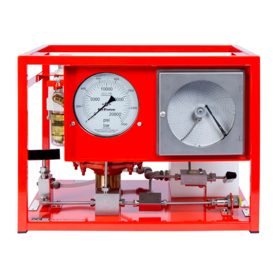
AHP3 SERIES – Hydrotest Pumps:
1.0 General Description
The Hi-Force AHP3 range of Hydrotest pumps
are supplied in a range of 3 models with output
pressures ranging from 42 bar(609psi) to 700bar
(10000psi) and are suitable for use with various
fluids including water.
2.0 Before operating your Hi-Force Hydraulic
Power Pack please ensure that the following
instructions are carried out.
1.
Connect the liquid supply to the pump
inlet port (1 ¼" NPT.) This is normally from a
reservoir tank.
2.
Ensure that the liquid is filtered before
reaching the pump unit liquid inlet port.
3.
Hydraulic oil (ISO 10 or 32) or water
can be used. When using water, a Glycol
additive to the water will reduce seal wear in
the unit.
4.
Check the air lubricator bottle is filled
(use any light grade lubricating oil –SAE 15). To
top up undo the screw on top of the bottle and
top up.
(Important Safety note: Ensure the air supply is
disconnected when filling the bottle.)
5.
The lubricator is factory set to deliver 1
drop every 25 strokes of the pump. The red
knob is used to affect this setting.
6.
Connect the air supply line to the
pump inlet (1/2" BSP) Min recommended pipe
size ½ bore. Air requirement is 70-100psi, 56
S.C.F.M. Ensure the air on/off valve is closed.
7.
The item requiring hydraulic pressure
connection may now be connected to the
outlet block. ½" NPTF
NB use only fittings and tubing, suitable for the
maximum pressure performance of the pump.
Once the above instructions have been
completed the Power Pack is ready for use and
the following operating procedure can be
followed:-
1.
Make sure the Isolator valve and
pressure let down valve is open and
the air pressure regulator is turned fully
anticlockwise. Direct the drain hose
into a suitable location as fluid will be
Hi-Force Limited – Prospect Way – Daventry – Northants NN11 8PL – United Kingdom
Tel: +44(0) 1327 301000: Fax: +44(0) 1327 706555: Website: www.hi-force.com
ATDP216,
discharged from this once the pump
starts.
2.
Open the air on/off valve and turn the
regulator clockwise until the pump
starts to cycle. Increase the air pressure
until the pump is running at around 100
cycles per minute. Allow the pump to
cycle for approximately two minutes,
this will purge the pump of any air.
3.
NB: This will not normally purge air from
the item under test. Additional vent
points (or other precautions) will be
required to ensure the item under test is
completely filled with liquid before
pressurisation otherwise a dangerous
situation may occur.
4.
Stop the pump by closing the air on/off
valve. Should any black oil be visible
around the pump air motor exhaust,
this should not give rise to concern, as
lubricated air is fed to the pump, and
excess oil will be discarded via the
exhaust.
To apply hydraulic pressure:-
5.
Close the pressure let down valve.
6.
Make sure the isolation valve is open.
7.
Turn the air pressure regulator valve
fully anticlockwise.
8.
Open the air ON/OFF valve and
gradually increase air pressure by
turning the pressure-regulator
clockwise until the pump starts to
cycle. This will deliver liquid to the item
under test and (once all vent ports are
closed) allow hydraulic pressure to
build up. The pressure may build up
very slowly depending on the size of
the item under test. This pressure will be
indicated on the large pressure gauge.
9.
The hydraulic output pressure is directly
proportional to the air inlet pressure.
The pump will stall when the hydraulic
pressure reaches a balance point
directly related to the air pressure
setting. To increase the hydraulic
pressure further, the air pressure must
be increased.
10. This feature can be used to maintain
pressure in a vessel over a period of
time. The pump will cycle occasionally
to keep the pressure topped up
against slight leakage loss.