Hi-Force ATDP63 Instrukcja obsługi - Strona 11
Przeglądaj online lub pobierz pdf Instrukcja obsługi dla Pompa wodna Hi-Force ATDP63. Hi-Force ATDP63 15 stron. Air driven hydrotest pumps
Również dla Hi-Force ATDP63: Instrukcja obsługi (9 strony)
8.2 Operation
1) Check that the pump on/off air valve is closed, and that the hydraulic pressure release valve is in the
open position.
2) Adjust the pump air pressure-regulating valve anticlockwise until it is fully wound out. Switch on the air
supply to the pump by external means.
3) Plug the hydraulic outlet connection.
4) Turn on the water supply to the pump. As long as the water supply is above approximately 0.7bar (10
psi) the water will flow through the pump and through the drain hose attached to the pressure release valve,
bleeding the system. If not (flowing water) turn the pump air pressure regulating valve slowly clockwise until
15-20 psi is shown on the air pressure regulators own air pressure gauge, the pump will operate pumping
the inlet water supply to drain.
5) Turn the pump air on/off valve to the off position and close the hydraulic pressure release valve once any
air bubbles, seen in the nylon drain hose, have disappeared and the system is bled properly.
6) To use the pump:
•
Open the pump air on/off valve.
•
Slowly adjust the pump air pressure-regulating valve clockwise, the pump will reciprocate and start
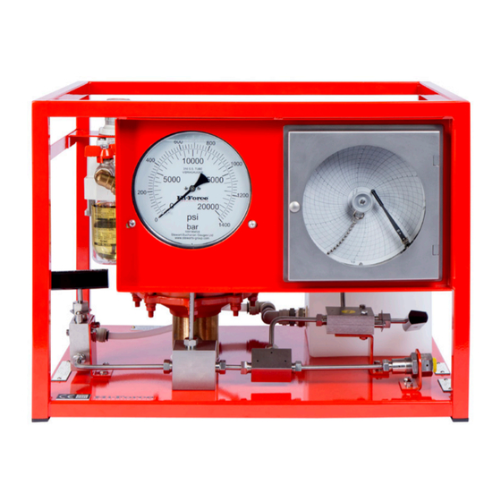
to displace fluid into the system and build up pressure, the pressure generated can be viewed on
the hydraulic pressure gauge.
•
The maximum pressure achievable at various air pressures can be seen in the Hi-Force catalogue
ATDP page under the heading "Max output pressure at airline input pressure" e.g. ATDP63 if 80 psi
air pressure is applied then the maximum pressure the pump can generate is approximately 80psi
x the pump ratio 63/1 = 5,040psi (347bar). ATDP125 if 80 psi air pressure is applied then the
maximum pressure the pump can generate is approximately 80psi x the pump ratio 125/1 =
10,000psi (700bar). ATDP216 if 80 psi air pressure is applied then the maximum pressure the pump
can generate is approximately 80psi x the pump ratio 216/1 = 17280psi (1191bar).
•
If a slower pump cycle rate is required the drive air pressure can be reduced by turning the air
pressure regulating valve anticlockwise and/or by partially closing the pump air on /off valve
•
The pump can operate as a transfer pump filling the vessel under test with liquid.
•
The pump will gradually and naturally start to cycle at a slower rate as the pressure in the vessel
under test increases until it stops (stalls) when a balance of forces is reached i.e. when the air drive
pressure x air drive piston area = stall pressure x driven hydraulic piston area.
•
The pump will hold pressure indefinitely unless a leak occurs, at which time the pump will
automatically cut in once the leak rate reaches a certain level to try to maintain the pressure in the
system.
Operating Instruction Manual:
OM-ATDP-01
11
From Serial Number:
All