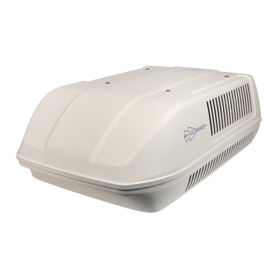
Aircommand Cormorant MKII Instrukcja instalacji i obsługi - Strona 6
Przeglądaj online lub pobierz pdf Instrukcja instalacji i obsługi dla Klimatyzator Aircommand Cormorant MKII. Aircommand Cormorant MKII 16 stron. Aircommand cormorant mkii rooftop air conditioner

- 1. Owners Manual
- 2. Warranty of Refrigerated Airconditioning
- 3. Serial Number
- 4. Main Components
- 5. Before Installation
- 6. Installation Position
- 7. Direction of Travel
- 8. Rear of Unit
- 9. Connect Electrical Supply
- 10. Installation Is Now Complete
- 11. Commissioning of the Unit
- 12. Maintenance
- 13. General Specifications
- 14. Display Setting
1. INSTALLATION POSITION
Minimum 25mm clearance from
side grills to any obstruction
Minimum 200mm clearance from
rear grills to any vertical face
Minimum 100mm clearance to any
45 degree face
Before beginning, mark out the position of the
unit considering the following important
requirements:
- The air conditioner should be situated as
centrally as possible on the van, to ensure even
air distribution.
- The front of the unit MUST face the direction
of travel; failure to follow this instruction will
result in damage to the condenser fans.
- If the caravan is over 23' in length, or has an
unusually high heat load (see General
Operating
Information
expectations
about
Aircommand would recommend 2 or more
units to cool effectively.
- When considering the installation position
remember to check for clearance around the
plenum inside the van.
- Avoid an installation position where a
bulkhead, cupboard or light fitting could
interfere with the discharge air flow from the
plenum.
It is important that the unit is never
more than 5° from the horizontal and
the rear of the unit should never be
higher than the front
- Contact Aircommand if your installation
differs significantly
DIRECTION OF TRAVEL
section
regarding
insulation
etc.),
- The above outline on the left shows the minimum clearance required around the
CORMORANT unit on the roof of the vehicle, distances shown are calculated from a
14" square hole (356 x 356mm)
- The above outline on the right shows the minimum clearance required around the
Plenum located on the ceiling inside the vehicle, distances shown are calculated from a
14" square hole (356 x 356mm)
Fig 1: CORMORANT Vent clearances
DIRECTION OF TRAVEL
160
170
450
Fig 2: The foot print of the rooftop unit, and the plenum, measured from the hole
REAR OF UNIT
160
14" x 14"
(356mm)
SQUARE
HOLE
DIRECTION OF TRAVEL
