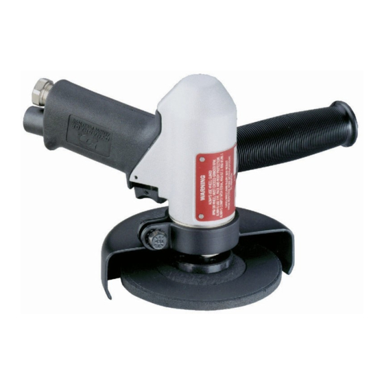
Dynabrade 50340 Skrócona instrukcja obsługi - Strona 3
Przeglądaj online lub pobierz pdf Skrócona instrukcja obsługi dla Narzędzia Dynabrade 50340. Dynabrade 50340 4 stron. 4-1/2"–5" pistol grip depressed center wheel grinder

Mounting Arrangement for 5" Diameter Type 27 Depressed Center Wheels
Type 27 Wheels — 5" Diameter
Type 27 Guard
Spacers
(as req.)
07138 Back Flange
Torque 28N•m/250 in. - lbs.
Type 27
Depressed Center Wheel
(not included)
07139 Front Flange
Important: Manufacturer's warranty is void if tool is disassembled before warranty expires.
Warning: The governor in this tool is preset at the factory to maintain the maximum rated speed for the tool, any repairs to this assembly should be
done at the Dynabrade factory. A motor tune-up kit is available (P/N 96047) to help maintain motor in peek operating condition.
Tool Disassembly:
1. Remove flanging, 55046 Guard Assembly and 53163 Side Handle.
2. Place machine housing in soft jaw vise. Important: Be careful not to overtighten vise to prevent damage.
3. Turn 55029 Cover clockwise and remove.
4. Pull motor assembly from housing.
5. Remove 56028 Muffler Cap. Use a 12mm hex key to unscrew 57066 Muffler Body and 57075 Cone Muffler from housing.
6. Unscrew 01494 Inlet bushing and remove.
Motor Disassembly:
1. Secure motor in a vise using flats on 55034 Adapter.
2. Screw governor assembly clockwise to remove from rear of motor.
Note: Any shims between the governor and back of rotor must be kept and replaced during reassembly.
3. Press rotor from 02649 Bearing and 01743 Bearing Plate.
4. Press 02649 Bearing from 01743 Bearing Plate.
5 Remove 01028 Cylinder and 01185 Blades (4) from rotor.
6. Secure 55025 Rotor in soft jaw vise.
7 Unscrew 55034 Adapter and remove from rotor.
8. Remove 01007 Front Bearing, 55026 Bearing Plate and 01010 Spacer from rotor.
9. Remove 01007 Bearing from 55026 Bearing Plate.
Valve Disassembly:
1. Drive 96025 Pin through housing and remove valve assembly from housing.
2. Remove trigger/valve assembly from housing.
3. Remove first 55051 Valve Stop (Press valve stem from valve stop, be careful not to damage 55041 Valve. A small bearing puller is recommended).
4. Remove 55041 Valve and separate.
5. Press 55042 Valve Stem through the second 55051 Valve Stop.
Valve Reassembly:
1. Slide 55039 Bushing (with o-rings) onto valve stem/trigger assembly.
2. Press 55051 Valve Stop onto 55052 Valve Stem large end out.
3. Install 55041 Valve onto valve stem.
4. Install 96147 O-Ring onto the 55051 Valve Stop.
5. Press 55051 Valve Stop onto valve stem with o-ringed end facing valve. Press valve stop until flush with valve stem end.
6. Reinsert into housing and replace 96025 Pin.
Disassembly/Assembly Instructions
(continued on next page)
Type 27 Wheels 5" diameter and smaller with 7/8" diameter arbor
holes may be mounted between matched flanges, provided the
matched flanges are at least 1-5/8" diameter or one third
diameter of wheel.
Important Safety Information
1. Always use eye, face and body protection.
2. Always use wheel guard.
3. For safe use of this tool, always comply with OSHA,
ANSI Standards B7.1 and B186.1.
4. Some wheels are supplied with throwaway adapters
(mounting flanges) attached by the manufacturer. These
adapters should not be used again.
Warning: Do not remove wheel guard.
3
