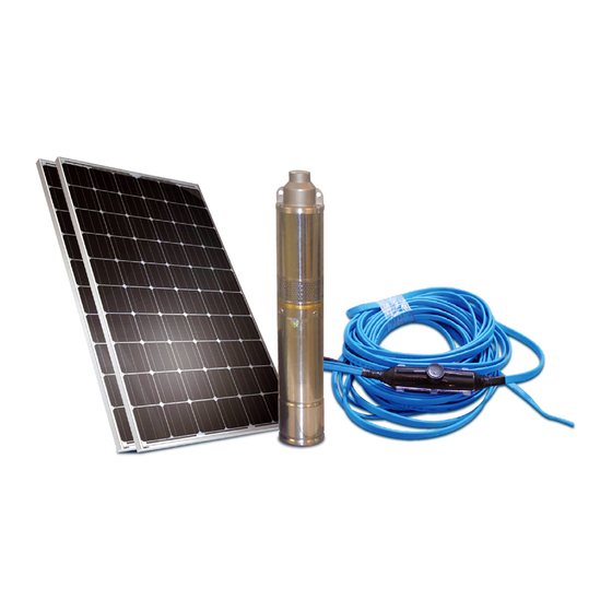
DAYLIFF SUNFLO-S 150 Instrukcja instalacji i obsługi - Strona 8
Przeglądaj online lub pobierz pdf Instrukcja instalacji i obsługi dla Falownik DAYLIFF SUNFLO-S 150. DAYLIFF SUNFLO-S 150 17 stron. Solar pumping systems

Modules should be wired as per the arrangement shown in Fig. 3,4 & 5 depending on
system. Note most systems are series connected +ve to -ve terminals, though larger
systems include parallel arrays. All module cables should be firmly connected with the
provided plugs to avoid short circuits.
The module connection cable should be connected to the PV Isolator that is provided with
MCB overload protection. All wiring connections should be made with the isolator 'off'.
SunFlo-S System Layout
PV MODULES
SunFlo-A System Layout
PV MODULES
Charge
DC Isolator
Batteries
Controllers
SunFlo-S 150 - 1 PV MODULE
SunFlo-S 300 - 2 PV MODULES
DC ISOLATOR
MODULE CONNECTIONS
SunFlo-A 150H - 1 PV MODULE
SunFlo-A 270H - 2 PV MODULES
SunFlo-A 600H - 4 PV MODULES
5
Outlet
Fig.3
OUTLET
Fig.4
