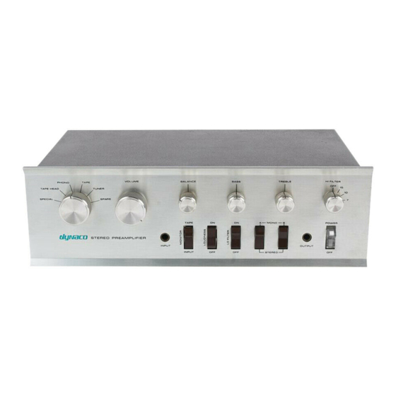
DYNACO PAT-4 Instrukcja montażu - Strona 5
Przeglądaj online lub pobierz pdf Instrukcja montażu dla Wzmacniacz DYNACO PAT-4. DYNACO PAT-4 20 stron. Power supply
Również dla DYNACO PAT-4: Instrukcja montażu (16 strony)

Section 2: Line Amp Distortion Reducer
Line Amp Characteristics
The line amp in a properly working PAT-4 has about 0.02% distortion when driving a
100K Ohm load at 1 Volt RMS. Typical units measure about -74 dB for the second
harmonic of a 1 kHz test signal, and perhaps -90 dB for the third harmonic. Distortion
increases for lower impedance loads and at higher levels.
By making the modification described herein, you can drop the 2
dB below the fundamental, and make the 3
about 0.002% distortion, rivaling the best preamps. Distortion reduces with reduced
output level.
How the Distortion Reduction Works
This modification changes Q4, a standard bipolar transistor, for the T0-92 Darlington
transistor and heat-sink supplied in the kit. The Darlington transistor greatly diminishes
the loading of the output stage on the first gain stage, increasing the overall open loop
gain. This leaves the closed loop gain essentially unchanged, but reduces distortion by a
factor of nearly 10.
The Modification in a Nutshell
You will be replacing Q4 with the supplied transistor and heat sink. If you're quite
familiar with the PAT-4, that's probably all you need to know. Otherwise, you may find
the information in the following sections helps you keep your place and avoid trouble.
Preparing to Remove the Circuit Boards
1. Disconnect the PAT-4 from your music system.
2. Unplug the power cord and allow the preamp to sit for one minute before moving
on.
Caution: Be sure that the preamp power is unplugged! 120 VAC can be lethal! 240 VAC
3. Remove the 4 screws that hold the cover in place, 2 on the left side and 2 on the
right side.
4. Lift the cover straight up and set it aside in a safe place.
5. Get masking tape and a pen ready. You will be labeling the wires that you are
about to remove.
6. Desolder the following wires from the left channel PC board, the one closer to the
back of the preamp. As you remove each wire, place a clearly marked masking
tape label on the wire with the number of the eyelet from which the wire was
removed. If you think it's helpful, add the letter R or L to the tag to designate
Right or Left channel. It may be easier instead to use F or B for front or back PC
Board. Don't put too much stress on the selector switch as you remove these
wires.
a. Eyelet 1
b. Eyelet 2
rd
harmonic invisible. That corresponds to
can be lethal!
Page 5 of 20
nd
Harmonic to about 94
