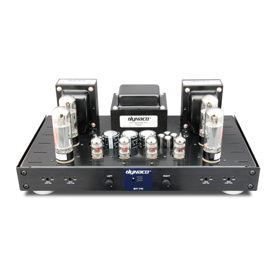
DYNACO ST-70 Instrukcja montażu - Strona 6
Przeglądaj online lub pobierz pdf Instrukcja montażu dla Wzmacniacz DYNACO ST-70. DYNACO ST-70 14 stron. Driver 6gh8 ecf82 for the ab-q-st70 auto bias module
Również dla DYNACO ST-70: Instrukcja instalacji i obsługi (9 strony)

If you have not as yet built the VTA driver board please do so now and when completed come back
to this point in your instruction manual. The instructions for building the VTA driver board are with
the board.
1. Obtain the hardware set for the VTA driver board and locate the four 4-40 5/8 inch long stainless
steel screws. Place the four screws in from the TOP of the chassis. Place a 4-40 NON KEP nut
on the other end from the inside of the chassis and screw it down to the bottom of the inside of
the chassis but DO NOT TIGHTEN THE SCREW. Make a "test fit" of the driver board. If it won't fit
on the screw ends then move the screws around slightly until the board fits properly. Tighten
the 4-40 nut firmly into position. Now place ANOTHER 4-40 NON KEP nut on top of the first nut
and tighten this nut on top of the first nut. The purpose of the TWO NUTS is to space the VTA
board down slightly into the chassis so the 4 outboard 270K resistors do not touch the chassis.
Make a final test fit and then remove the board.
2. Solder one end of FOUR 1 ¾ inch wires onto the board into the four input eyelets in the center
front of the board. The two UNMARKED holes nearest the edge of the board are GROUND
connectors. (S) The other two connectors are marked "R-IN" and "L-IN". (S) After soldering all
four wires to the board bend the 4 wires slightly towards the center of the board to facilitate the
installation of the board. NOTE: If you have Russian PIO coupling caps on your driver board it is
easier NOW to connect ONE END of four 3 ½ inch wires (shorten them to the correct length
later) to the four UNMARKED HOLES AT THE TWO SIDES of the driver board that are about 7/8"
in from the front and back of the board. CONNECT THEM to THE BOTTOM OF THE DRIVER
BOARD and solder them in on the BOTTOM of the driver board. These are the four wires listed
in steps 5 and 6 under the section "Connections to the VTA Driver Board" on the next 2 pages.
3. Slide the VTA board onto the 4 screws until it bottoms out on the doubled up nuts. The four
input wires you just soldered should be FACING THE FRONT of the amp. Tighten down the
board this time WITH four 4-40 KEP nuts. Make sure that the two pair of twisted wires from V3
and V6 do not get caught under the board and are BEHIND the two front 5/8 inch screws that
hold the board. NOTE - The pictorial shows these twisted wires above the front power takeoff
sockets but they should run BELOW the two power take off sockets as viewed from the
underside. The color photograph shows the correct routing of these wires.
4. Obtain the two tube sockets that will fit into the power take off holes in the front of the chassis.
Bend the tube socket pins in against the back of the tube socket slightly. Bend towards the
BACK of the amp slightly the two front .22 Mfd orange drop coupling capacitors (or Russian PIO
capacitors) on the driver board to gain some clearance. Install the LEFT power takeoff socket
with 4-40 hardware. Install the RIGHT power take off socket with 4-40 hardware. Both are a tight
fit but will go in to their respective holes.
5. Install the slide switch that fits into the stereo/mono slot with 4-40 hardware. This switch will
NOT BE USED and NOT CONNECTED to the ST-70 circuitry in any way but it fills the front
rectangular slot to give the front face of the amp a better appearance.
6. Assemble the input terminals onto the input board. Place the input jack in from one side. Next,
place the ground tab, then a washer and then the nut from the other side of the input board.
Tighten the nut securely keeping the ground tabs to the bottom or side. Bend the ground tabs
out slightly at a 45 degree angle to make the electrical connections that will come later easier.
Install the input board with the input terminals from the INSIDE with the 4-40 hardware provided.
