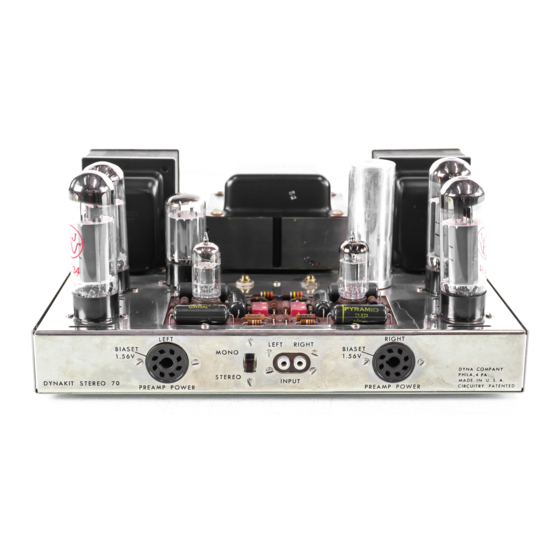
DYNACO Stereo 70 Podręcznik przywracania - Strona 3
Przeglądaj online lub pobierz pdf Podręcznik przywracania dla Wzmacniacz DYNACO Stereo 70. DYNACO Stereo 70 20 stron. Series ii tube amplifier
Również dla DYNACO Stereo 70: Podręcznik przywracania (5 strony), Instrukcja obsługi (12 strony), Instrukcje montażu (16 strony)

Page 3
electrolytic capacitors will continue to store and present even after you have removed the
power and disconnected the line cord. Once again, always assume that lethal voltages are
present and work accordingly. That means never place yourself in a position to be the
conductor between the circuit and ground (let the jumper become the more direct current
path).
II. Stereo 70 Overview :
Although not mandatory, it will be very helpful for you to understand the operation of
your Stereo 70 and the three principal functional sections and how they interact. The next
section discusses each section briefly.
Tube power amplifiers are relatively simple devices and consist three main sections:
1) The Power Supply – The power supply consists of
a. The line cord,
b. Fuse & Fuse Holder
c. Power switch,
d. Power transformer,
e. Rectifier (tube is stock, modified may be diodes) & Tube Socket
f. Choke,
g. Filter capacitor (the Quad electrolytic "can"), and
h. Bias supply. The Bias supply consists of the rectifier diode (in the original
it was a selenium "stack"), filter capacitors (2), fixed resistors (2), and bias
pots (2, one for each channel).
Because the power supply is common to both channels, symptoms that effect both
channels (dead amp, fuse tripping, hum in both channels, weak power in both
channels, etc.) is usually the result of a problem in the power supply.
2) The Output Stage – There are two output stages, one for each channel. Each
output stage consists of :
a. the output transformer,
b. output tubes (2 per channel), and
c. cathode bias resistor (the original value was 15.6 ohms and had the
appearance of a white ceramic tubular device connected to pins 1 & 8 of
both output tubes).
d. The output tube sockets should also be considered a "component" in the
output stage – they have a higher incidence of failure than the typical
mechanical component due to the constant high temperature exposure.
That's it – really simple. It is important for you to know that the output stage
tubes are meant to conduct a little "bias" current when the amp is idle. This bias
current is controlled by placing a negative voltage at the control grid (pin 5 of the
EL34 output tubes). Note - if this negative voltage were to disappear, the control
Dynaco Stereo 70 Power Amplifier
Restoration Manual
Detailed Procedure & Guide
R0 4-03
3
