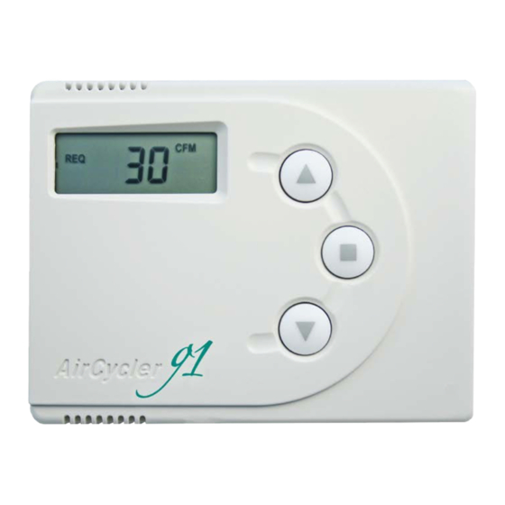
AirCycler g1 Instrukcja instalacji i obsługi - Strona 3
Przeglądaj online lub pobierz pdf Instrukcja instalacji i obsługi dla Kontroler AirCycler g1. AirCycler g1 11 stron. Ventilation controller
Również dla AirCycler g1: Podręcznik testowania instalacji (2 strony)

WIRING DIAGRAM
KEY
R - 24VAC Power
C - Common
Gt - Fan From Thermostat
Gf - Fan To Furnace
V - Vent
Vnc - Normal Closed Vent
SELECTING YOUR COMPONENT EQUIPMENT
AIR HANDLER
The 2012 IECC requires the central blower used with the AirCycler® g1 to use an electronically commutated motor.
AIR HANDLER
Y
R
C W
G
3
AirCycler® g1
THERMOSTAT
Y
R
W G
OPTIONAL
Blue
DAMPER
Red
White
AC DOC
REV 9/14/2016
