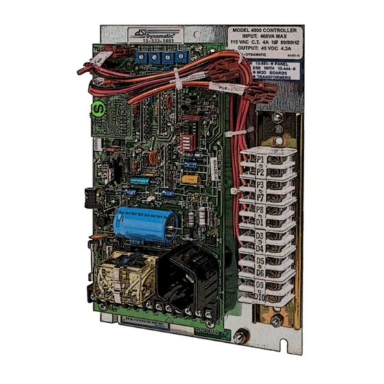
Dynamatic 15-539-0015 Arkusz instrukcji - Strona 7
Przeglądaj online lub pobierz pdf Arkusz instrukcji dla Kontroler Dynamatic 15-539-0015. Dynamatic 15-539-0015 14 stron.

Modification PCB Mounting
If you have purchased a complete controller this section may be passed over and you may proceed to
General Description.
1. Place the Main PCB in front of you with the long dimension in a horizontal position and the
terminal strip to the left.
2. Remove the DIP switch by pulling it straight out of the receptacle, RECP 1. Then, peel the adhesive-
backed label off the other half of RECP 1.
3. Insert the arrow-type locking head of the four nylon stand-offs supplied into the four 0.188"
diameter holes in the main PCB and press in. The tabs will snap out to lock the stand-offs
permanently in position.
4. Hold the modification PCB assembly over the stand-offs with the ribbon connector toward you
and insert the ribbon connector plug into RECP 1. Be careful to see that all 16 pins are started
properly into the receptacle before pressing the plug in.
5. Align the holes in the modification PCB assembly over the stand-offs and press over the tapered
posts until the locking flanges snap out to lock the board in position.
General Description
For some variable speed drive applications, it is necessary to limit the torque available to a machine in
order to prevent damage to the machine itself or its process. The Torque Limit modification provides and
"override" feedback signal which indirectly limits the induction motor torque (current) to a preset
maximum value. This limit can be used to prevent the motor breakover torque from being reached during
a condition such as drive output shaft 'lock-up" or the period when a large system inertia is being
accelerated. The adjustment range is from 50 to 150% of rated motor torque.
Preliminary Adjustments
Perform the following preliminary adjustments (which no power applied to the controller)
1.
Operator Controls
a. Set the Run Speed potentiometer R5 to 0% (Full CCW)
b. Set the Jog/Run selector switch to the Run position
c. Note location of Start and Stop pushbuttons
2.
Main PCB 15-530-5 or 15-530-6
The pots used are screwdriver adjust, single turn pots. Do not use a screwdriver with a blade width
exceeding 1/8" in width.
a. Set the Accel Rate potentiometer R18 to 100% (Full CW)
b. Set the Zero Adjust potentiometer R19 to 0% (Full CCW)
c. Set the Max Speed/Volts potentiometer R21 to 0% (Full CCW)
d. Set the Velocity Damping potentiometer R22 as follows (see trimpot illustration):
e. Set the Time Constant (TC) Adjust potentiometer R26 as follows (see trimpot illustration):
7
(supplied by customer unless specified)
