dB Technologies DVA T12 Podręcznik użytkownika - Strona 5
Przeglądaj online lub pobierz pdf Podręcznik użytkownika dla System głośników dB Technologies DVA T12. dB Technologies DVA T12 18 stron.

CHARACTERISTICS AND PROTECTION
Front Grille
The speakers's components in the box are protected by 1.2mm metal steel grille covered
by foam on backside.
Cooling
Thermal control is managed by the main microprocessor that interacts with the local
microprocessors (amplifiers and power supply) and communicates the data to the DSP for
any corrections.
If the amplifier module heats up excessively, the volume is gradually reduced step wise to
0.1dB until the module is thermally stabilised.
The volume is automatically restored when the normal operating temperature is reached.
Power on
The diffusor is powered up normally by an initialization process during which the module is
powered by the auxiliary power supply.
When all of the amplifier peripherals are correctly detected, the main power supply is
activated.
The technology (RANDOM POWER ON ) introduces a random and differentiated delay for
each module prior to the power on of the main PSU (Power Supply Unit).
This prevents the breakaway starting currents of the various modules from accumulating,
overloading the AC power supply line.
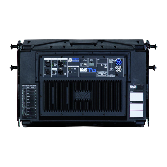
At the end of the power on procedure, only the green "READY" LED will remain on fixed on
the amplifier module.
Failure indications and safeties
The microprocessor is able to signal three different kinds of failure by flashing the "LIMTER" red
LED on the amplifier panel before the lighting up of the "READY" green LED. The three types of
failure are:
1)
WARNING: a non severe error or auto-ripristinate malfunction is detected and the
performance of the speaker is not limited
2)
LIMITATION: an error is detected and diffuser performance is limited. The sound level is
reduced or one or more amplifiers are disabled.
This state partially influences the correct functioning of the diffuser.
If the problem persists the next time the module is turned on, contact the support
centre for assistance.
3)
FAILURE: a severe malfunction is detected. The speaker switches to "mute".
If the case of a malfunction, before contacting the support centre, try to turn the module off
and on to check if the problem still exists.
Connecting to the mains supply
Each active speaker features its own power cable. Connection is done by a Neutrik
POWER CON® (blue) model which permits easy and fast connection to the speaker as
well as being an excellent locking system.
The same connector serves as a switch to turn ON and OFF the active loudspeaker by
turning the connector to the left (OFF) or right (ON).
The active speaker must be connected to a power supply able to deliver the maximum
required power.
Main power supply linking
On the rear of the speaker, a Neutrik POWER CON® connector (grey) offers linking the
mains power supply.
This socket links the power supply to another speaker, thereby reducing the direct
connections to the mains. Maximum amplifier input power is shown on the amplifier panel.
The maximum number of speakers connected together varies of max input power and of
the maximum allowed current of the first power socket.
12
