Celexon PL400 HC plus Instrukcja instalacji - Strona 5
Przeglądaj online lub pobierz pdf Instrukcja instalacji dla Akcesoria do projektorów Celexon PL400 HC plus. Celexon PL400 HC plus 9 stron. Projector lift

Turn the screw A on the motor clockwise to lower
the upper 'stop position' (see fig 6).
To set the lower 'stop position':
Turn the screw B on the motor clockwise to reduce
the lower 'stop position' (see fig 6). To turn the
screw anticlockwise, it will increase the lower 'stop
position'. (Max descend: 30cm).
The PL400 ceiling lift is supplied with two additional
safety screws that prevent the lift to extend beyond
the lower 'stop position' in case of a mechanical
failure or damage to the steel cables. If the lower
'stop position' has been changed, place the safety
screws into the right position and proceed as follows:
1 Once the lower 'stop position' has been set (as
per instructions above), extend the lift up to the
lower 'stop position'.
2 Adjust the safety screws to the correct positions
(see fig 7). In order to do that, loosen the safety
screws and position them 3mm from the floating
point of the scissor joint system.
3 Tighten the safety screws on both sides.
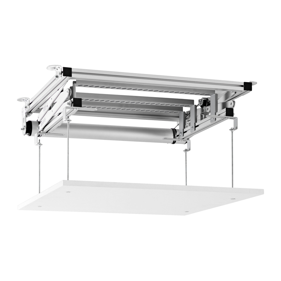
Once the 'stop positions' have been set, attach the 4
L mounting brackets with the screws supplied (D and
M) to the lift (see fig 8). The threaded bars can be cut
to the correct length if required. Use the M6 nuts to
tighten the L brackets.
Attach the 4 threaded ceiling panel screws (or
ceiling panel screws) (L1/L2) to the ceiling panel (in
the correct position) (see fig 9). Once the ceiling
panel has been attached, check the fit of the ceiling
cut-out. The panel must not drag on the cut out and
must be aligned centrally.
4
fig. 6
fig. 7
fig. 8
fig. 9
