Autonics PA10-VP Instrukcja obsługi
Przeglądaj online lub pobierz pdf Instrukcja obsługi dla Kontroler Autonics PA10-VP. Autonics PA10-VP 2 stron. Multifunctional sensor controller
Również dla Autonics PA10-VP: Skrócona instrukcja obsługi (8 strony)
DRW171160AA
SENSOR CONTROLLER
PA10 SERIES
I N S T R U C T I O N
Thank you for choosing our Autonics product.
Please read the following safety considerations before use.
Safety Considerations
※Please observe all safety considerations for safe and proper product operation to avoid hazards.
※Safety considerations are categorized as follows.
Warning Failure to follow these instructions may result in serious injury or death.
Caution Failure to follow these instructions may result in personal injury or product damage.
※The symbols used on the product and instruction manual represent the following
symbol represents caution due to special circumstances in which hazards may occur.
Warning
1. Fail-safe device must be installed when using the unit with machinery that may cause serious injury or
substantial economic loss. (e.g. nuclear power control, medical equipment, ships, vehicles, railways, aircraft,
combustion apparatus, safety equipment, crime/disaster prevention devices, etc.)
Failure to follow this instruction may result in fire, personal injury, or economic loss.
2. Install on a device panel or DIN rail to use.
Failure to follow this instruction may result in electric shock or fire.
3. Do not connect, repair, or inspect the unit while connected to a power source.
Failure to follow this instruction may result in electric shock or fire.
4. Check 'Connections' before wiring.
Failure to follow this instruction may result in fire.
5. Do not disassemble or modify the unit.
Failure to follow this instruction may result in electric shock or fire.
Caution
1. When connecting the power/sensor input and relay output, use AWG 24 (0.20mm
cable or over and tighten the terminal screw with a tightening torque of 0.98 to1.18N . m.
Use proper cables for the rated load current.
Failure to follow this instruction may result in fire or malfunction due to contact failure.
2. Use the unit within the rated specifications.
Failure to follow this instruction may result in fire or product damage.
3. Use dry cloth to clean the unit, and do not use water or organic solvent.
Failure to follow this instruction may result in electric shock or fire.
4. Do not use the unit in the place where flammable/explosive/corrosive gas, humidity, direct sunlight, radiant
heat, vibration, impact, or salinity may be present.
Failure to follow this instruction may result in fire or explosion.
5. Keep metal chip, dust, and wire residue from flowing into the unit.
Failure to follow this instruction may result in fire or product damage.
▣ Ordering Information
PA10
U
No mark NPN input
Input
P
PNP input
U
High function controller
Function
V
Controller
W
2 Channel controller
Item
PA10
Multi-function power amplifier
▣ Input Connections
PA10-U
PA10-V/PA10-W
●
●
NPN open
NPN open
collector
collector type &
Sensor
Sensor
output
NPN universal
type sensor
controller
controller
output type sensor
+12V
+12V
⑨, ⑬
1.8㏀
IN1, IN2
IN1, IN2
⑪ IN1
(
⑮ IN2
9.4㏀
0V
0V
⑩
(
⑭
※The above specifications are subject to change and some models may be discontinued without notice.
※Be sure to follow cautions written in the instruction manual and the technical descriptions
(catalog, homepage).
▣ Specifications
Model
Power supply
Allowable voltage range
Power consumption
Power for external
sensor
M A N U A L
Input(IN1, IN2)
Input method
Contact output
Out-
Solid-state
put
output
Response time
Time setting
function by
Have
each mode
※Only for
PA10-U
Non
Relay
Mechanical
life
Electrical
cycle
Dielectric strength
Insulation resistance
Ambient
Envi-
temperature
ron
Ambient
ment
humidity
Unit weight
※If the load is connected over 200mA at the sensor output, it may cause mechanical trouble.
※Environment resistance is rated at no freezing or condensation.
▣ Dimensions and Installation Interval
◎ Dimensions
Ø5
2
) to AWG 15 (1.65mm
2
)
OUT1
OUT2
PA10-U
OR
AND
NORM
INV
NORM
INV
IN 1
NORM
SA
IN 2
M
O
O
SB
O
F
D
SC
F
N
E
SD
POWER
A
TIME
O
T1
D
F
O
J
N
T2
F
MADE IN KOREA
▣ Connections
※Use teminals of size specified below.
a b
<Forked>
PA10-U
●
Brown
9
Black
+12V
Brown
Blue
+12V
13
PA10-VP/PA10-WP
●
OUT1
PNP open
PA10-U
collector type &
Sensor
PNP universal
controller
output type sensor
+12V
POWER
!
5.4㏀
5
IN1, IN2
SOURCE
100-240VAC
~
5.6㏀
50/60Hz
0V
1
CONTACT OUT:
250VAC 3A
RESISTIVE LOAD
PA10-U
PA10-V
PA10-VP
PA10-W
100-240VACᜠ 50/60Hz
90 to 110% of rated voltage
Max. 10VA (condotion:12VDC/200mA resistive load)
12VDCᜡ ±10% approx. 200mA
Selectable NORM/INV.
Selectable OR/AND
Selectable NORM/INV.
Selectable NORM/INV.
operation for IN1, IN2
Selection function for
Operation for IN1, IN2 AND.
input. Selection function
IN1, IN2 individual operation.
for IN2 derivative action.
NPN input type
NPN input type
PNP input type
NPN input type
PA10-U
●
[No-voltage input] Impedance at short-circuit: Max. 680Ω, Residual voltage at short-
circuit: Max. 0.8V, Impedance at open: Min. 100kΩ
PA10-V/PA10-W
●
[No-voltage input] Impedance at short-circuit: Max. 300Ω, Residual voltage at short-
circuit: Max. 2V, Impedance at open: Min. 100kΩ
PA10-VP/PA10-WP
●
[Voltage input] Input impedance: 5.6kΩ, "H" level voltage: 5-30VDCᜡ, "L" level voltage: 0-2VDC
OUT[250VACᜠ 3A(Resistive load)]
OUT1, OUT2 [250VACᜠ 3A(Resistive load)]
OᆞC OUT1, OᆞC OUT2
OᆞC OUT
-
NPN open collector output Max. 30VDCᜡ Max. 100mA
Relay output : Max. 10ms, Transistor output : Max. 0.05ms
ON-DELAY MODE
OFF-DELAY MODE
●
●
ONE-SHOT DELAY MODE
FLICKER MODE
●
●
FLICKER ONE-SHOT MODE
LOW-SPEED DETECTION MODE
●
●
HIGH-SPEED DETECTION MODE
ON/OFF-DELAY MODE
●
●
NORMAL MODE
FLIP-FLOP MODE
ENCODER(MODE 9 to 11)
●
●
●
Min.10,000,000 times
Min.100,000 times(250VAC 3A resistive load)
2000VAC 50/60Hz for 1 minute
Over 100MΩ(at 500VDC megger)
-10 to 55℃ [Storage: -25 to 60℃]
35 to 85%RH [Storage: 35 to 85%RH]
Approx. 150g
Approx. 160g
◎ Installation interval
(
: mm)
Unit
When installing multiple sensor
82
38
controllers, please keep space
between units at least 10mm for
heat radiation.
35.5
a
b
Min.
Max.
3.5mm
7.0mm
PA10-V/PA10-VP
PA10-W/PA10-WP
●
●
Brown
Brown
Blue
Blue
Black
Black
Black
Black
10
11
12
9
10
11
12
OᆞC
OᆞC
Blue
GND
IN1
+12V
GND
IN1
+12V
OUT1
Blue
OUT
OᆞC
Brown
Brown
GND
IN2
+12V
GND
IN2
+12V
OUT2
14
15
16
13
14
15
16
OUT2
OUT
OR
AND
PA10-V
NORM
INV
NORM
INV
IN 1
IN 1
NORM
NORM
INV
SA
NORM
INV
M
IN 2
IN 2
O
O
SB
O
F
D
SC
F
N
E
SD
POWER
POWER
A
TIME
O
T1
O
D
F
J
N
T2
F
MADE IN KOREA
MADE IN KOREA
!
!
6
7
8
5
6
7
8
SOURCE
SOURCE
100-240VAC
~
100-240VAC
~
NC
COM
NO
NC
COM
NO
50/60Hz
50/60Hz
2
3
4
1
2
3
4
CONTACT OUT:
CONTACT OUT1,OUT2:
250VAC 3A
250VAC 3A
RESISTIVE LOAD
RESISTIVE LOAD
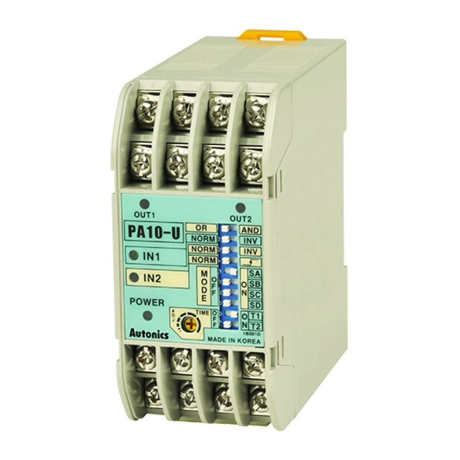
▣ Front Panel Indentification
PA10-WP
PA10-U
●
Power indicator : LED turns on when AC power applied
1
!
Output indicator 1 : Indication of output 1 operation status
2
Output indicator 2 : Indication of output 2 operation status
3
Sensor input indicator : lndication of sensor input signal
9
10
11
12
4
OᆞC
+12V
GND
IN 1
OUT1
AND/OR selection switch : Select "AND" or "OR" for IN1, IN2 Input
5
OᆞC
+12V
GND
IN 2
Selection switch of sensor input signal
6
OUT2
3
13
14
15
16
:
NORM
2
5
NORM : When input signal is low, it is valid signal. (
OUT 2
●
OUT 1
OR
AND
●
INV : When input signal is high, it is valid signal. (
PA10-U
PNP input type
NORM
INV
6
Derivative action selection of IN2 input signal (AND/OR selection switch: AND)
NORM
INV
7
IN 1
NORM
4
7
:
SA
IN 2
M
O
O
SB
O
8
●
NORM : IN2 input signal is operating as reverse turn function
F
D
SC
F
N
E
1
SD
●
POWER
O
T1
A
O
9
D
F
8
Selection switch for operation mode: See "▣ Operation mode" in next page.
J
F
N
T2
0
Selection switch of time range and max. input frequency: It is the switch
MADE IN KOREA
9
5
6
7
8
to select time range(1 to 7 mode) or allowable input frequency(9 to 11 mode).
O
F
F
NC
COM
NO
O
F
F
1
2
3
4
O
F
F
O
F
F
Timer volume: Adjust time within the range which is set with
0
Terminal block
!
●
PA10-V/PA10-VP
5
Power indicator
1
: LED turns on when
9
10
11
12
AC power applied.
OᆞC
+12V
GND
IN 1
Output indicator
2
OUT
: Indication of output
+12V
GND
IN 2
signal.
13
14
15
16
Sensor input indicator
3
2
: lndication of sensor
OUT
input signal.
PA10-V
PA10-V: LED turns on
●
IN 1
when sensor input is Low
INV
NORM
3
4
NORM
INV
PA10-VP: LED turns on
●
IN 2
when sensor input is High
Selection switch of
POWER
4
1
sensor input signal
MADE IN KOREA
NORM: When sensor
●
5
6
7
8
input signal is Low,
it is vaild signal.
INV: When sensor input
●
NC
COM
NO
signal is High, it is vaild
1
2
3
4
signal.
Terminal block
5
Min. 10mm
※When IN1, IN2 input signal is AND, OUT will work.
▣ Derivative Action Applications
◎ Detect label of glass bottle
BEN300-DDT
IN2
(Sensor for
Brown
synchroni-
zation)
Brown
Blue
Black
IN1
(Sensor for detecting
the target)
BEN300-DDT
!
SOURCE
100-240VAC
~
50/60Hz
Blue
Operation
●
Black
When IN1 is ON and IN2 is ON, OUT will not work.
9
10
11
12
But when there is no label on bottle, OUT will work when IN2 is ON. OUT will be returned after setting time.
GND
IN1
Note)Condition of detecting label on glass bottle is to install with IN1 operating first.
GND
IN2
13
14
15
16
▣ Factory Default for S/W
OUT1
OUT2
PA10-W
PA10-U:
●
●
PA10-V: NORM
IN 1
NORM
INV
MODE1 ON-DELAY
PA10-VP: NORM
●
NORM
INV
OUT2
IN 2
OUT1
OUT2
OUT
OR
AND
PA10-U
PA10-V
MADE IN KOREA
NORM
INV
5
6
7
8
NORM
INV
NC2
COM2
NO2
IN 1
NORM
NORM
SA
NC1
COM1
NO1
M
IN 2
O
O
SB
O
1
2
3
4
F
D
SC
N
F
E
OUT1
SD
POWER
POWER
T1
A
TIME
O
O
F
D
N
T2
J
F
MADE IN KORE A
(LED turns on when sensor input is Low)
(Input signal reverse turn function)
INV
)
)
(When input signal is high(
), it is effective signal)
NORM
: Derivative action of IN2 input signal. ※See "▣ Derivation action applications"
T1
O
Time range: Approx. 0.01 to 0.1sec, Max. input frequency: 100kHz
●
N
T2
T1
Time range: Approx. 0.1 to 1sec, Max. input frequency: 10kHz
O
●
N
T2
T1
O
Time range: Approx. 0.1 to 10sec, Max. input frequency: 1kHz
●
N
T2
T1
Time range: Approx. 10 to 100sec, Max. input frequency: 100Hz
O
●
N
T2
.
9
●
PA10-W/PA10-WP
Power indicator
6
1
: LED turns on when AC
power applied
9
10
11
12
Output 1 indicator
2
+12V
GND
IN 1
: Indication of output 1
operation status.
+12V
GND
IN 2
Output 2 indicator
3
: Indication of output 2
13
14
15
16
operation status.
2
3
OUT1
OUT2
Sensor input indicator
4
PA10-W
: lndication of sensor
input signal.
IN 1
PA10-W: LED turns on
NORM
INV
5
●
4
NORM
INV
IN 2
when sensor input is Low.
PA10-WP: LED turns on
●
when sensor input is High.
POWER
1
Selection switch of
5
MADE IN KOREA
sensor input signal
5
6
7
8
NORM: When sensor
●
input signal is Low,
NC2
COM2
NO2
it is vaild signal.
●
INV: When sensor input
NC1
COM1
NO1
signal is High, it is vaild
1
2
3
4
signal.
Terminal block
6
※IN1, IN2 operates individually.
IN1
Label
No label
(Sensor for
ON
detecting
OFF
the target)
OᆞC
Blue
IN2
Black
OUT1
ON
(Sensor for
OFF
synchronization)
9
10
11
12
ON
Derivative action
OFF
13
14
15
16
T
OᆞC
OUT1
OUT2
ON
PA10-U
OR
AND
OUT2
OUT (3-4)
NORM
INV
OFF
NORM
INV
IN 1
NORM
SA
IN 2
M
ON
O
O
O
SB
F
D
SC
OUT1
F
N
E
SD
OFF
POWER
TIME
O
T1
A
O
D
F
N
J
F
T2
MADE IN KOREA
OᆞC OUT1
ON
5
6
7
8
(10-12)
OFF
1
2
3
4
ON
OUT2
OFF
OᆞC OUT2
ON
Output((OUT)
(14-16)
OFF
PA10-W: NORM
●
PA10-WP: NORM
●
OUT1
OUT2
PA10-W
IN 1
IN 1
NORM
INV
NORM
INV
NORM
INV
NORM
INV
IN 2
IN 2
POWER
MADE IN KOREA
MADE IN KOREA