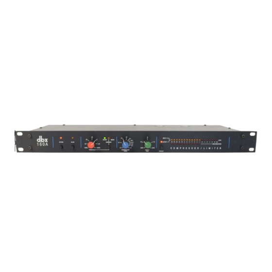
dbx 160A Instrukcja obsługi - Strona 9
Przeglądaj online lub pobierz pdf Instrukcja obsługi dla Wzmacniacz dbx 160A. dbx 160A 20 stron. Compressor limiter
Również dla dbx 160A: Broszura i specyfikacje (2 strony)

+24dBu. This jack accepts 1/4" phone plugs. In normal operation the TRS phone jack is internally wired with the TIP
HOT (+), and the RING and SLEEVE connected to ground. In Bypass mode, however, the RING is connected to the
COLD (-) leads of the input jacks, to allow for balanced connections.
GROUND (GND) Lift Switch:
This switch allows for troubleshooting hum (line interference) caused by ground loops. In the "GND" position, pin 1 of the
input XLR-type jack is connected to the 160A's chassis ground. In the "LIFT" position it is disconnected.
DETECTOR INPUT Jack:
This Tip/Ring/Sleeve phone jack accepts a standard TRS 1/4" phone plug, and is of the "normalling" type (i.e., when a
phone plug is inserted, the detector input is no longer connected in parallel with the audio input.) The DETECTOR INPUT
jack accepts balanced or unbalanced sources, independent of other jacks.
METER CALIBRATION Control:
This screwdriver-adjustable trimmer may be used to precisely calibrate the front panel's upper LED display so a 0dB
INPUT or OUTPUT indication is equivalent to any signal from -15dBu (138mVRMS) to+10dBu (2.45VRMS).
STEREO STRAPPING Jack:
When a TRS (Tip/Ring/Sleeve) 1/4" phone plug patch cable is inserted between two 160As, stereo strapping can be
achieved by depressing the SLAVE switch on one unit only. This will provide accurate processing for stereo programming.
AC Power Jack:
This jack accepts an IEC-type power cord (as shipped with the unit). Plug the cord into the unit and mains power. Note
that the 160A does not have a power switch. It is recommended that the 160A be "On" at all times. Power consumption is
low. If you do not plan to use the 160A for an extended period of time, unplug it.
Warning: Be sure to verify both your actual line voltage and the voltage for which your Model 160A was wired, as indicated on
the rear panel of your unit. Connection to an inappropriate power source may result in extensive damage which is not covered
by the warranty.
OPERATING NOTES
Basic Operation
Using the THRESHOLD Control
In Hard Knee mode (OVEREASY button out), THRESHOLD sets a reference level above which input signals will be pro-
cessed by the 160A's gain change circuitry in the manner defined by the setting of the RATIO control. Input signals which
fall below this level will pass through the 160A unprocessed (except for fixed gain changes directed by the OUTPUT
GAIN control). See Figure 1.(Page 4)
In OverEasy Mode (OVEREASY button depressed), signals begin to gradually activate the 160A's gain change circuitry as
they approach the THRESHOLD reference level and they do not get fully processed in the manner defined by the RATIO
control until they have passed somewhat above the THRESHOLD reference level. In OverEasy mode there is no distinct
point at which processing begins, and the THRESHOLD setting corresponds to a point on the input/output transfer curve
midway between the onset of processing and that point at which the transfer curve corresponds to the setting of the RATIO
control. Figure 2 shows the OverEasy compression curves and how they correlate with the THRESHOLD LEDs.
Note: The THRESHOLD setting always relates to the signal level seen by the 160A's DETECTOR circuitry. In normal operation (i.e., sending audio to the
INPUT jack only), the 160A actually responds to the DETECTOR INPUT which is wired internally in parallel to the INPUT. This concept is important to
understand because the parallel connection is broken when you insert signal into both input jacks. In this case, as you might suspect, the signal present at
the DETECTOR INPUT determines how the 160A processes the signal coming into its INPUT (refer to Sidechain Applications, page 8) Note that the
DETECTOR INPUT does not feed signal to the OUTPUT and therefore cannot be used as a substitute for the INPUT.
Using the COMPRESSION RATIO Control
When an input signal is above the THRESHOLD reference level, the setting of this control determines the number of deci-
bels by which the input signal must change in level to produce a 1dB increase in the signal level at the output of the 160A.
A setting of 2:1 indicates an input:output ratio wherein a 2dB increase in signal (above threshold) will produce a 1dB
increase in output signal. A setting of ∞:1 indicates that an infinite increase in input level would be required to raise the
output level by 1dB. In other words, the output level stays constant when the input signal rises above threshold.
The 160A's RATIO control covers the entire range from 1:1 to ∞:1 and, in addition, goes to Infinity+ (negative) ratios. At
a setting of -1:1, the above threshold input signal must increase by 1dB in level to decrease the signal at the output of the
dbx 160A COMPRESSOR / LIMITER
5
