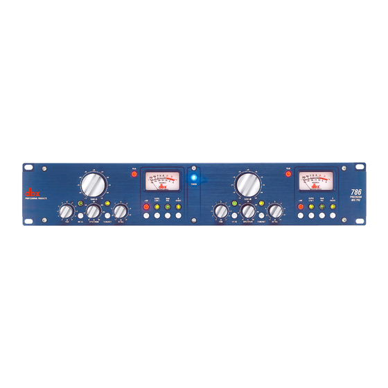
dbx 786 Instrukcja obsługi - Strona 9
Przeglądaj online lub pobierz pdf Instrukcja obsługi dla Wzmacniacz dbx 786. dbx 786 16 stron. Precision mic preamp

dBr
A: 16dB Cut @ 5kHz; 6dB/Octave Slope
B: 16dB Cut @ 5kHz; 12dB/Octave Slope
C: -∞ Cut @ 5kHz; 6dB/Octave Slope
D: -∞ Cut @ 5kHz; 12dB/Octave Slope
Figure 4: Audio Precision plots of the 786's EQ section.
Peak LED
The Peak LED is located to the left of the VU Meter. It is set to light when the signal level is within
3dB of hard clipping. The LED monitors three different points in the signal path: output of the Gain
control stage, the output of the Fine control stage, and the output of the EQ stage.
VU Meter
The VU Meter is a custom dbx meter and monitors the output signal of the 786. It is calibrated at
0VU=+4dBu.
+48V Phantom Power Switch and LED
This switch activates phantom power for condenser microphones on pins 2 and 3 of the XLR mic input.
Make sure to connect your microphone before activating the phantom power to prevent high voltage
arching, which may damage your microphone.
Super Low Z Input Switch and LED
Typically microphones have an output impedance of 150Ω. The 786 is set to operate in this range with-
out any adjustments necessary. In some instances, a microphone may operate at a much lower imped-
ance, like 20Ω. (ie: some ribbon microphones) The Super Low Z switch optimizes the input circuit of
the 786 for proper damping of these low impedance microphones, and to ensure that the input trans-
former is always fed by the same impedance for consistent performance.
20dB Pad Switch and LED
This switch inserts a 20dB attenuator circuit into the signal path from the microphone input. The pad is
inserted before the signal is routed through the mic pre gain stage. Use the 20dB pad to attenuate sig-
nals from hot sources such as high output microphones, or when the source is a line level device.
Phase Reverse Switch and LED
This switch inverts the phase of the input source 180°. Note that it usually takes years of engineering
experience to properly hear phase relationships. If your console has a phase relationship meter, you may
choose to do "A-B" comparisons with the phase reverse switch in both positions for best results. Out of
phase signals are more obvious in the lower frequency range, due to the size of the waveforms. Out of
phase signals may sound "empty", "hollow", or "weak" in the low frequencies. Use the phase reverse
switch to determine if the source device is out of phase with the rest of the program material.
dBr
A
B
C
D
controls
786
A: 16dB Boost @ 12kHz; 12dB/Octave Slope
B: 16dB Boost @ 12kHz; 6dB/Octave Slope
C: 16dB Cut @ 12kHz; 6dB/Octave Slope
D: 16dB Cut @ 5kHz; 12dB/Octave Slope
Operating
A
B
C
D
7
