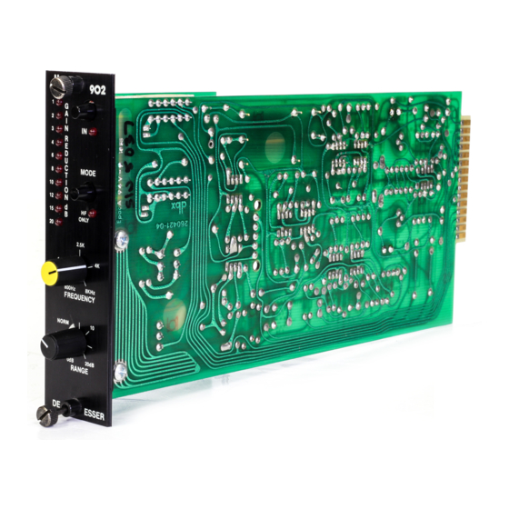
dbx 902 Podręcznik - Strona 6
Przeglądaj online lub pobierz pdf Podręcznik dla Sprzęt komputerowy dbx 902. dbx 902 8 stron.

4
the 902 with the grounding methods described in the previous sections. If the problem persists, try connecting a
jumper wire between B- and ground. This should cure the popping sound, but the signal will now be unbalanced in
the OUT, or BYPASS mode and hum may increase.
C
ONNECTIONS FOR
Skip this step if you do not intend to use any of the 902 special applications listed below. Refer to the listed page for
information and installation steps for each application.
F
P
RONT
ANEL
Figure 2: 902 Front Panel
1
G
A
2
I
N
IN
3
R
4
E
D
6
U
8
C
MODE
T
10
I
O
12
N
15
HF
d
B
ONLY
20
2.5K
1.8K
800Hz
8KHz
FREQUENCY
NORM
10
0dB
20dB
RANGE
DE-
ESSER
A
PPLICATIONS
One of the primary design goals for the 902 de-esser is to eliminate the need for any adjustments when de-essing a
wide variety of vocal material. However, several other interesting and worthwhile effects can be obtained with the
user controls provided. By adjusting the filter cutoff frequency and the maximum amount of gain reduction, the high
end of certain percussive source material can be altered on a dynamic basis. For example, the pick noise on a gui-
tar track can be completely eliminated without affecting the timbre of the guitar. When a guitar string is struck, the
first sound produced is a high level, high frequency ÒclickÓ, with the amplitude of the fundamental string vibration
building up relatively slowly. By processing a guitar track through the de-esser, the track can be brightened consid-
erably via normal high-frequency boost equalization without exaggerating annoying pick noises.
S
A
PECIAL
PPLICATIONS
U
T
E
SING
HE
XTERNAL
The CV input and output connections come from the factory jumpered together for normal de-esser operation. To
use the CV input, this jumper (R74) must be removed. Jumper R74 is shown in figure 1 on page 3. Figure 3 on
page 5 illustrates a way of setting up the external wiring to the 902 using normalling type connectors so the CV
input can be accessed when necessary.
S
A
PECIAL
PPLICATIONS
O
PERATIONS
G
R
LED
AIN
EDUCTION
IN/OUT S
:
Allows the user to hardwire bypass the 902 for before/after comparisons.
WITCH
Controls and indicators continue to function in the bypass mode. For de-essing it
should be left in the normal mode.
MODE S
:
Allows the 902 de-essing action to affect either the entire audio band-
WITCH
width, or the high frequencies only. For de-essing it should be left in the normal
mode. For Òde-edgingÓ and Òde-clickingÓ of some instrumental material it should
be put in the HF ONLY mode.
FREQUENCY C
ONTROL
into high and low frequency portions for evaluation. The 902 detects sibilant
material by comparing (in dB) the high frequency level of an audio signal and the
full bandwidth level of the signal. When the high frequency level is excessive rel-
ative to the full bandwidth level, the 902 will de-ess. For normal vocal de-essing,
this control should be set around the 12:00 position (2.5 kHz) position. For spe-
cial processing of instrumental material, the control should be swept back and
4K
forth until the optimum setting is obtained.
RANGE
C
ONTROL
ed. For normal vocal de-essing, leave this control in the NORMAL region.
Turning the RANGE control clockwise beyond the NORMAL region will cause
vocal sibilants to be excessively attenuated or Òswallowed.Ó More extreme set-
tings are useful for special effects and for processing instrumental material.
Since the 902 is effectively inaudible in normal Òde-essingÓ operation (sibilants simply sound
normal) there may be a tendency to turn the range control clockwise beyond the normal
region. Prolonged listening will, however, reveal the extra de-essing effect as unnatural for
vocals.
C
V
I
ONTROL
OLTAGE
NPUT
:
Indicate the amount of de-essing in dB.
S
:
Selects the frequency at which the 902 splits the audio signal
: Sets the amount of de-essing effect produced when a sibilant is detect-
(D-)
¨
902
