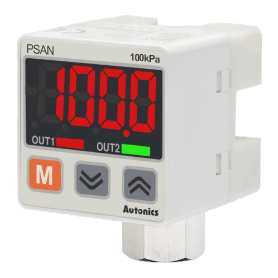
Autonics PSAN-L01CV Series Podręcznik - Strona 12
Przeglądaj online lub pobierz pdf Podręcznik dla Przyrządy pomiarowe Autonics PSAN-L01CV Series. Autonics PSAN-L01CV Series 13 stron. Small size, 1/2,000 resolution connector type digital pressure sensor
Również dla Autonics PSAN-L01CV Series: Podręcznik (2 strony)

▶ When Auto shift function is used
When Auto shift input signal remains at low level more than
1ms, the measured pressure at this point will be saved as
a reference value to make correct judgment regardless of
pressure changes. Corrected preset pressure value will be
applied after 7.5ms.
Measured reference pressure value will be saved in [ ShIN ]
Flashing twice when
input Auto shift signal
Auto shift
input
Min. 1ms
Switch
output
response
Min. 7.5ms
(Switch output Response time
when Auto shift signal is input)
※When Auto shift function is used, the possible set pressure
range will be wider than rated set pressure range.
※The possible set pressure range for Auto shift type
models.
Pressure
Set pressure range
type
Vacuum
-101.3kPa to 5.0kPa
pressure
-5.0kPa to 110.0kPa
Vacuum
pressure
-50.0kPa to 1100kPa
Compound
-101.3kPa to 110.0kPa -101.3kPa to 110.0kPa
pressure
※ If the set point value corrected by auto shift input exceeds
set pressure range,an error message will flash three times
and corrected value is not saved.
→[-HH-] displayed when the set point value corrected by
Auto shift input is above the upper limit of set pressure
range.
→ [-LL-] displayed when the set point value corrected
by Auto shift input is below the lower limit of set pressure
range.
※ The correction value will be saved in EEPROM.
▶ Example of Auto shift function
< When Auto shift is not used >
Normal primary
Drop of primary
pressure
Pressure
pressure
h
ON
OUT
OFF
Time
Time
Time
Preset point value will be
corrected by Auto shift input.
Possible set pressure range
for Auto shift type models
-101.3kPa to 101.3kPa
-110.0kPa to 110.0kPa
-1100kPa to 1100kPa
Increase of primary
pressure
Time
Time
Pressure Sensor
< When Auto shift is used >
Normal primary
Drop of primary
Pressure
pressure
ON
OUT
OFF
Auto shift input
Reference pressure =
Reference pressure ≤
Atmospheric pressure
Atmospheric pressure
(0.0kPa)
Correction set value: [ ST1]' = [ ST1] + [ ShIN]
Correction set value: [ HYS1]' = [ HYS1] + [ ShIN]
※ [ ShIN] is the reference pressure set by Auto shift input.
Key lock function
The key lock function prevents key operations so that
conditions set in each mode.
• LOC1 : All keys are locked; therefore it is not available to
change parameter settings, preset value, zero adjustment,
High/Low peak check, and ShIN data initialization. (Lock
setting change is available)
• LOC2 : Partially locked status; therefore it is not available
to change parameter settings only(Lock setting change is
available). Other settings are still available.
• OFF : All of the setting is available, all keys are unlocked. to
set detection sensitivity automatically at proper position.
Zero-point adjustment function
The key lock function prevents key operations so that
conditions set in each mode.
The zero-point adjustment function forcibly sets the pressure
value to "zero" when the pressure port is opened to
atmospheric pressure. When the zero adjustment is applied,
analog output [Voltage or Current] is changed by this function.
(Press
+
keys over 1 sec. in RUN mode.)
High Peak / Low Peak Hold function
This function is to diagnosis malfunction of the system
caused by parasitic pressure or to check through memorizing
the max./min. pressure occurred from the system.
Error
Description
display
When external pressure is
ERR1
input while adjusting zero
point
When overload is applied on
ERR2
control output
When setting condition is not
ERR3
met in Auto sensitivity setting
mode
When applied pressure
LLLL
exceeds Low-limit of display
pressure range
When applied pressure
HHHH
exceeds High-limit of display
pressure range
-HH-
-LL_
Auto shift correction error
-HO_
Increase of primary
pressure
pressure
Time
Time
Auto shift input
Reference pressure ≥
Atmospheric pressure
(0.0kPa)
(0.0kPa)
Troubleshooting
Try again after removing
external pressure
Remove overload
Check setting conditions and
set proper setting values
Apply pressure within display
pressure range
Set the corrected setting
value within setting pressure
range.
E-15
(A)
Photo
electric
sensor
(B)
Fiber
optic
sensor
(C)
Door/Area
sensor
(D)
Proximity
sensor
(E)
Pressure
sensor
(F)
Rotary
encoder
(G)
Connector/
Socket
(H)
Temp.
controller
(I)
SSR/
Power
controller
(J)
Counter
(K)
Timer
(L)
Panel
meter
(M)
Tacho/
Speed/ Pulse
meter
(N)
Display
unit
(O)
Sensor
controller
(P)
Switching
power
supply
(Q)
Stepping
motor&
Driver&Controller
(R)
Graphic/
Logic
panel
(S)
Field
network
device
(T)
Software
(U)
Other
