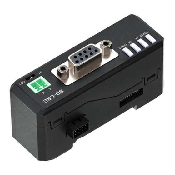
Autonics BD-C Series Instrukcje - Strona 2
Przeglądaj online lub pobierz pdf Instrukcje dla Konwerter mediów Autonics BD-C Series. Autonics BD-C Series 3 stron. Laser displacement sensor communication converter

Proper Usage
Before using this communication converter unit,depending on the usage environment,
keep following items handy.
Visit our web site (www.autonics.com) to download.
• atDisplacement program, manual
• Communication converter SCM Series Driver, instruction manual
Manual
For the detail information and instructions, please refer to the manual, and be sure to
follow cautions written in the technical descriptions (catalog, website).
Visit our website (www.autonics.com) to download manuals.
atDisplacement
• atDisplacement is a PC software for BD series laser displacement sensors. It is
available for parameter setting, monitoring and data management.
• Visit our website (www.autonics.com) to download the user manual and the program.
Product Composition
Amplifier
unit
External
cable
Sensor
• Measuring displacement of object
head
• Using power from the amplifier unit
Specifications
Model
BD-CRS
Power supply
-
01)
≤ 2.3 W
Power Consumption
Communication
Modbus RTU
Protocol
Connection type
RS-232C, RS-485
Communication speed
9600, 19200, 38400, 115200 bps (default)
Executes every BD-Series feature, sets parameter and real-time
Function
monitoring by external device (Master)
Ambient temperature
-10 to 50 ℃, Storage: -15 to 60 ℃ (no freezing or condensation)
Ambient humidity
≤ 85%RH, Storage: ≤ 85%RH (no freezing or condensation)
1.5 mm amplitude at frequency of 10 to 55 Hz (for 1 min) in each X, Y,
Vibration
Z direction for 2 hours
Shock
300 m/s
(≈ 50 G) in each X, Y, Z direction for 3 times
2
Protection structure
IP40 (IEC standard)
Material
Case: PC
Accessory
Side connector, Connector for RS485
Sold separately
Communication converter: SCM Series
Approval
ᜧ ᜣ ᜫ
Unit weight (packaged) ≈ 49 g (≈ 91 g)
01) Using power from the amplifier unit. To use BD-C Series communication converter, the amplifier unit needs 12-30
VDCᜡ power supply.
• It is recommended to use Autonics communication converter. Please use twisted pair wire, which is suitable for
RS485 communication.
Dimensions
• Unit: mm, For the detailed drawings, follow the Autonics website.
25
• BD Series manual
• Setting parameter and
communication input/output
• Connecting 1 sensor per 1 unit
• Mutual connection: ≤ 8 units
• Supporting communication function
Communication
• Connection to amplifier unit: ≤ 8 units
converter
• Using power from the amplifier unit
• Extending connection distance between
sensor head and amplifier unit
75
Unit Descriptions
2
4
5. Communication setting switch
Refer to 'Communication setting - Communication setting switch'.
6. Status Indicator
POWER TX
RX ERROR
Display
Name
Color Status Description
(Color)
Power is
On
supplied.
POWER
Power
green
(Green)
Off
Power is not supplied.
Communi
Flash
Signal is outputting.
TX
-cation
green
(Green)
Off
Signal is not outputting.
output
Communi
Flash
Signal is inputting.
RX
-cation
green
(Green)
Off
Signal is not inputting.
input
Connection is bad
between communication
On
converter and amplifier
unit.
Communi
ERROR
Communication is bad
-cation
red
(Red)
between communication
error
Flash
converter and amplifier
unit.
Off
Operation is normal.
Connections
■ RS232C
• When connecting BD-C to external device, use D-SUB 9 pin cable.
BD-C
5
4
3
2
1
9
8
7
6
Pin Name Function
1
N.C.
-
Converter
2
TXD
output signal
Converter input
3
RXD
signal
4
N.C.
-
5
GND
Ground signal
6
N.C.
7
N.C.
-
N.C.
8
9
N.C.
■ RS485
Communication pin
Terminating switch
RT
Set the switch to 'RT' when the communication
1
2
converter is connected to the terminal of RS485
communication connection, and set to 'OFF' when it is
Pin Name Function
in the middle of the communication connection.
1
A(+)
RS485 + signal
2
B(-)
RS485 - signal
1. RS485 terminating switch
Refer to 'Connection - RS485 -
1
terminating switch'.
2. RS485 connector
Refer to 'Connection - RS485 -
3
Communication pin'.
6
3. RS232C connector
Refer to 'Connection - RS232C'.
4. Side connector
A connector for connecting between
5
communication converter and
amplifier unit.
Troubleshooting
-
After checking the connection
between communication
converter and amplifier unit
correctly, reconnect the device.
-
-
-
-
After checking the connection
between communication
converter and amplifier unit
correctly, reconnect the device.
Apply noise prevention to
communication converter and
amplifier unit.
-
External device
5
4
3
2
1
9
8
7
6
Pin Name
1
CD
2
RD
3
SD
4
ER
5
SG
6
DR
7
RS
8
CS
9
CI
FG
OFF
