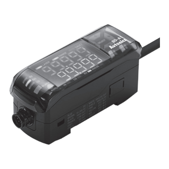
Autonics BD Series Instrukcja obsługi produktu - Strona 3
Przeglądaj online lub pobierz pdf Instrukcja obsługi produktu dla Czujniki bezpieczeństwa Autonics BD Series. Autonics BD Series 6 stron. Laser displacement sensors amplifier unit
Również dla Autonics BD Series: Podręcznik (14 strony), Instrukcja obsługi produktu (5 strony), Instrukcja obsługi produktu (3 strony)

Unit Descriptions
■ Sensor head
Power indicator (red)
Receiver
Emitter
Emission
center line
• Emission center line and the object should be aligned because the laser is emitted
along the line.
• For the details about indicators, refer to 'Indicator display'.
■ Amplifier unit
12
3
4
5
PV (present value) display ( red)
Displays PV (present value), calculating
1
result (when using calculation), parameter
name (when setting parameter).
SV (setting value) display (green)
Displays SV (HIGH, LOW, RV, Analog
output, Bank), parameter setting value
2
(when setting parameter). The type of
displaying SV can be recognized by SV
display recognition lamp.
Judgment indicator: HI/LO (red), GO
3
(green)
4 Alarm indicator (red)
5 Optimization setting key [AUTO]
[Amplifier unit] Connection
Color
Description
Brown
Power: 10 - 30 VDCᜡ
Blue
Common GND (Input/Output/Power)
Black
HIGH judgment output
Orange
LOW judgment Output
Gray
GO judgment Output
Green
Alarm output
White
Analog output
Shield
Analog output GND
01)
Pink
External input1
Yellow
External input2
Timing, Output reset, Laser OFF, Zero-point
adjustment, Bank A, Bank B, OFF
Red
External input3
Purple
External input4
01) It is needed to distinguish from common GND.
Control Output Diagram
■ Judgment (High, Go, Low) and alarm output
• NPN open collector output
LOAD
≤ 100 mA
OCP
30 VDCᜡ
SCP
LOAD
■ Analog output
+
+
mA
• OCP (Over Current Protection), SCP (Short Circuit Protection)
• The control output is abnormal when the control output circuit is
-
-
Laser emission
indicator (green)
NEAR/FAR indicator
(NEAR/FAR, green)
Out of the rated measurement range:
Flashing
Mounting
Near the reference distance:
hole
Turns ON.
Connector cable
11
10
▲
9
1
◀
▶
▼
2
6
7
8
SV display recognition lamp (green)
- HI: HIGH judgment value
6
- LO: LOW judgment value
- RV: Real distance value
- ANALOG: Analog output
Zero-point adjustment setting key
7
[ZERO]
8
Mode setting key [MODE]
9
Direction key [◀], [▶], [▲], [▼]
10 Calculation Indicator (CALC, green)
Measurement range Indicator
11
(RANGE, green)
Laser emission indicator (LASER,
12
green)
• PNP open collector output
LOAD
30 VDCᜡ
OCP
SCP
≤ 100 mA
shorted or over current is supplied.
Installation Procedures
No.
Chapter
Check reference
1
distance and select
mounting location.
Check the
2
precautions about
the measurement.
Check mounting
3
method and
mount.
Check and apply the
4
function of
amplifier unit.
[Sensor head] Mounting Location
Select mounting location regarding displacement of the object, reference distance and
measurement range. Mount sensor head where the object is located at the reference
distance by checking the operation of indicators and displacement value.
■ Indicator display
Check the operation of indicators to know distance between sensor head and the
object.
NEAR indicator (green)
FAR indicator (green)
Power indicator (red)
Laser emission
indicator (green)
■ Displacement indication
Item
Reference
Power
distance
Output
■ Indication by distance
• Unit: mm
Reference
Model
distance
External input
BD-030
30
BD-065
65
BD-100
100
LOAD
Description
As the distance between the sensor head and the object
approaches the reference distance, accurate measurements
can be made. Refer to 'Mounting Location' to select optimum
mounting location.
In case of measuring moving or rotating object, it is needed to
install the sensor head to correct direction. When measuring at
narrow area or concave object, it is needed to set the position of
the sensor head. For the details, refer to 'Installation Precautions'.
Mount to the panel directly or through the enclosed bracket.
Refer to ' Mounting and Connecting Method' to mount the sensor
head.
BD series support various settings and functions such as pitch
light optimization, zero adjustment setting, automatic sensitivity
setting, calculation through the amplifier unit.
Rated measurement range
Distance between
Reference
the sensor head
distance
and the object
OFF:
ON:
The value is displaced more positive (+) as the
object is closer to sensor head, more negative
value (-) as the object is far from sensor head
(+)
relative to the origin (0).
(0)
Rated measurement range
(-)
Indication
Rated measurement
range
NEAR ON
25 to 35
25 to 31
55 to 75
55 to 67
80 to 120
80 to 104
Reference distance±
( Rated measurement
range×10%)
Cross-flashing:
NEAR / FAR ON
FAR ON
29 to 31
29 to 35
63 to 67
63 to 75
96 to 104
96 to 120
