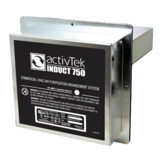
activTek INDUCT 2000LV Instrukcja obsługi - Strona 3
Przeglądaj online lub pobierz pdf Instrukcja obsługi dla Oczyszczacz powietrza activTek INDUCT 2000LV. activTek INDUCT 2000LV 17 stron. Electronic air purification system

INSTALLATION REQUIREMENTS
Installation Requirements
WARNING! - This unit must be installed by a licensed HVAC
contractor. Failure to do so will void warranty of the product.
1. Unit should be installed after the air handler in the
HVAC system.
2. The ductwork around the installation area should be
clean and dry to ensure proper adhesion of the gasket
materials and any tape used.
3. When installing near a furnace or heating coils, run the
heating system through three (3) full heating cycles to
ensure the temperature of the InDuct 2000 LV unit does not exceed 120˚F.
4. An approximate 3.5" (8.89 cm) opening will need to be cut into the existing
ductwork to install the unit properly.
Power Connection Requirements:
This device is designed for operation from a 24 VAC transformer typically supplied with
straight cool or HVAC systems and can accept a voltage input range of 18-32VAC. As these
transformers also power other circuits, the load capacity of the transformer must be verified
prior to installation to accommodate the maximum combined load requirements of both the
device (18 VA) and all other circuits powered from the transformer. The minimum voltage out-
put from the transformer under maximum load from all circuits including the device should
also meet the minimum voltage input requirements of each circuit's operational specification
including the device. If these conditions cannot be met, installation of a separate 24 VAC trans-
former is recommended. Do not connect this unit to any voltage source above 32 volts. Doing
so will cause damage to the unit.
NOTE: Unit requires continuous power. Do not install where power to the unit will be cycled
on and off.
METAL DUCTWORK INSTALLATION
1
1. Locate suitable area
of duct for installation.
3
3. Mark location for 3.5" opening using either the
mounting plate or included template.
4
Min. 9" x 9"
Metal Ductwork
Min. 10" x 10"
Fiberglass
Ductwork
Air
Handler
2
2. Cut away insulation to expose metal duct (if
needed).
4
4. Cut hole in duct using 3.5" hole saw.
ALTERNATIVE CUTTING METHOD
a
Max. 15 ft.
a. Using template, mark 4 Cutting Method
holes on duct.
METAL DUCTWORK INSTALLATION
5
5. Remove backing from
mounting plate adhesive gasket.
7
7. Secure the mounting plate using (8) #8 self-tapping
screws.
9
9. Secure the unit to the mounting
plate with (4) #8-32 nuts.
NOTE: Unit requires continuous
power. Do not install where power
to the unit will be cycled on and off.
b
b. Drill 4 holes where marked.
c
c. Cut between holes using tin snips.
(CONTINUED)
6
6. Center openings and press mounting plate onto duct.
The adhesive gasket will hold the mounting plate in
place.
8
1/4
8. Insert unit into opening. Be sure the air will pass though
10
the ActivePure® cell honeycomb matrix.
10. Power Connection Requirements:
This device is designed for operation from a 24 VAC transformer typically
supplied with straight cool or HVAC systems and can accept a voltage
input range of 18-32VAC. As these transformers also power other circuits,
the load capacity of the transformer must be verified prior to installation
to accommodate the maximum combined load requirements of both
the device (18 VA) and all other circuits powered from the transformer.
The minimum voltage output from the transformer under maximum
load from all circuits including the device should also meet the
minimum voltage input requirements of each circuit' s operational
specification including the device. If these conditions cannot be met,
installation of a separate 24 VAC transformer is recommended. Do not
connect this unit to any voltage source above 32 volts. Doing so will
cause damage to the unit.
5
