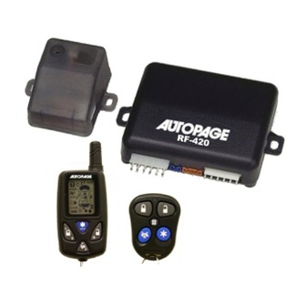
Autopage RF-420LCD Instrukcja instalacji - Strona 6
Przeglądaj online lub pobierz pdf Instrukcja instalacji dla Alarm samochodowy Autopage RF-420LCD. Autopage RF-420LCD 12 stron. Professional vehicle security system

8. WHITE/BLUE WIRE – PROGRAMMABLE OUTPUT –
CHANNEL 3 OUTPUT (Factory default setting)
This wire is built-in user-programmable timer output provides a ground through this wire.
Press the
+
button on the transmitter. You may program the built-in timer to send
a ground signal for any time interval between 1 second and 2 minutes. For instance, this
timer output may be used to turn on the headlight with the remote control. Also on certain
BMW, Mercedes Benz, Jaguar and Volkswagen cars, you can use this unique timed
output to allow remote closure of all power window and sunroof without the need for an
external module! (See Alarm Feature C – 2 Programming)
PAGER OUTPUT (See Feature C – 2 Programming)
This wire provides a negative output, when the alarm triggered. The current capacity of
this wire is 200mA. For optional electrical device in this system, please connected to an
additional relay. (I.E. Pager interface....)
9 . GRAY WIRE – (-) 200mA PROGRAMMABLE OUTPUT –
CHANNEL 2 OUTPUT (Factory default setting)
This will become a 2 seconds pulse ground by activate channel 2 on transmitter for two
seconds, the current capacity of this wire is 200 mA. This feature allows you to remote
control trunk release or other electric device. This output can also be programmed to
provide the following type of output: 2 sec. pulse, latched, timer control and pager. (See
Alarm Feature C - 1 Programming)
PAGER OUTPUT (See Feature C – 1 Programming)
This wire provides a negative output, when the alarm triggered. The current capacity of
this wire is 200mA. For optional electrical device in this system, please connected to an
additional relay. (I.E. Pager interface....)
10. WHITE WIRE – (-) 200mA DOME LIGHT CONTROL OUTPUT –
This wire becomes grounded when the dome light controls circuit active. The current
capacity of this wire is 200mA. This wire can control the operation of the interior lights.
An optional 10 Amps relay can be used to this system for interior lights operation.
a). Upon disarming, the interior lights will remain on for 30 seconds.
b). If the vehicle is violated, the interior light will flash for the same duration as the siren.
RF ANTENNA - BLACK THIN WIRE
The black thin wire on the control module is the receiver antenna wire. Antenna placement
is very important! Ensure that it is unwrapped and stretched out with the last 6" straight and
keep it away from large metal objects or chassis for best reception.
4-PIN BLACK CONNECTOR. –AM TRANSMITTING/ANTENNA MODULE
The transmitting/antenna mounting location should be the upper left
or lower left corner of driver's windshield. For optimum range we
suggest that the antenna be mounted as shown in picture to the
right. (Antenna tip facing up)
Warning!
Do not mount in such a manner that it obstructs the driver's view.
-Paging button used to page person in possession of the 2-Way
transmitter.
- Remove the protective tape backing.
- Carefully align the two-way transceiver/antenna and apply to windshield.
- Route the black connector wire behind the trim and connect to the two-way
transceiver/antenna.
- Connect the other end to the control module.
**Special considerations must be made for windshield glass as some newer vehicles
utilize a metal -shielded window glass that will inhibit or restrict RF reception. In
these vehicles, route the two ways transceiver/antenna module away from metallic
shielded window glass as far as possible.**
6
