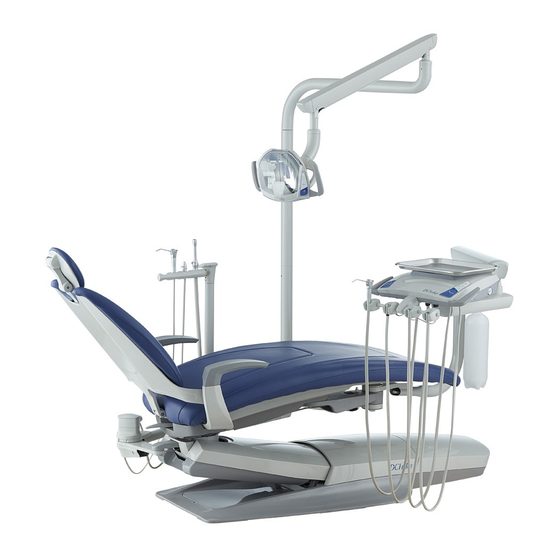
DCI Edge SERIES 4 Instrukcja instalacji - Strona 12
Przeglądaj online lub pobierz pdf Instrukcja instalacji dla Sprzęt medyczny DCI Edge SERIES 4. DCI Edge SERIES 4 14 stron. Dental chair
Również dla DCI Edge SERIES 4: Instrukcja instalacji (12 strony), Instrukcja instalacji (11 strony), Instrukcja obsługi (8 strony)

SERIES 4 DENTAL CHAIR
Installation Instructions
DIAGNOSTIC STATUS CODES
Status Codes are displayed on a two 7-segment display on
the chair control circuit board. These are visible through the
clear window of the protective cover. Errors are designated
with an 8 as the first digit. While there are error codes
displayed, no other status code will be displayed. When
more than one code's condition is present, each applicable
code will will be displayed, alternating every second.
POSITION CONTROLS
Display
Status
System Normal, No
00
current action
Keypad connected to
10
KEY1 is being pressed
Keypad connected to
11
KEY2 is being pressed
Keypad connected to
12
KEY3 is being pressed
Keypad connected to
13
KEY4 is being pressed
No motion in progress
14
while keypad is pressed
15
Backrest in motion
16
Base in motion
Auto-position in
17
progress
Auto-position in
18
progress
INDICATORS
Display
Status
Signal received to move
20
backrest but it has
reached its soft limit
Signal received to move
21
base but it has reached
its soft limit
Signal received to move
both base and backrest
22
but both have reached
their soft limits
Lamp is being activated
25
or deactivated
12
If this status is incorrect
Check Green LEDs are lit on the keypad
input board
1. Check keypad for a stuck key
2. Check keypad cables for damage creating
a short circuit
(normal function)
(normal function)
(normal function)
(normal function)
If this status is incorrect
Reprogram soft limits
Reprogram soft limits
Reprogram soft limits
1. Check keypad for a stuck key
2. Check keypad cables for damage creating
a short circuit
Display
Status
If this status is incorrect
1. Check the safety cover and ensure that it is free
to move up and down
2. Check that the safety cover properly activates
the switch
3. Check cable connections to the safety switches
Safety cover switch
30
engaged
attached to each side of the truss casting
4. Check cables connecting the switches for
continuity
5. Check that safety switches open the electrical
circuit when the lever is depressed
1. Check the air switch in the delivery head for
proper function
31
Auxiliary Switch engaged
2. Check keypad cable connecting the delivery
head Input Board to the Control Board
Display
Status
If this status is incorrect
Backrest Position value
80
too low
Backrest Position value
81
1. Check soft limits, reprogram as necessary
too high
2. Check for damaged sensor cables
3. Check to ensure the sensor is installed with the
Base Position value
82
text on the box being right side up
too low
Base Position value
83
too high
Software fault, watchdog
84
Replace Control Board if persistent
engaged
85
Base Sensor not found
1. Ensure that the sensor is connected to the
Control Board
86
2. Check sensor or input wiring for damage
Back Sensor not found
88
Harware fault
Replace Control Board if persistent
1. Check keypad connections both at the Control
Board and the Input Board to which the keypad
89
No keypads found
is connected
2. Check for damage to the keypad cables
F0
Fault on Base Port
F1
Fault on Base Port
F2
Fault on KEY1 Port
Check sensor or input wiring for damage
F3
Fault on KEY2 Port
F4
Fault on KEY3 Port
F5
Fault on KEY4 Port
1. If chair had reached its mechanical limit, adjust
Pump has overrun, chair
Pu
has been automatically
soft limits farther away from the mechanical limit
stoped
2. Check hydraulic system for leaks
SAFETY SWITCHES
ERRORS
