Dynatech PR-2000 UD Instrukcja obsługi i konserwacji - Strona 9
Przeglądaj online lub pobierz pdf Instrukcja obsługi i konserwacji dla Urządzenia przemysłowe Dynatech PR-2000 UD. Dynatech PR-2000 UD 18 stron.
Również dla Dynatech PR-2000 UD: Instrukcja obsługi (11 strony)

INSTRUCTIONS : PR-2000-UD
Date : 20/10/2020
Revision : 10
1 GENERAL INSTRUCTIONS
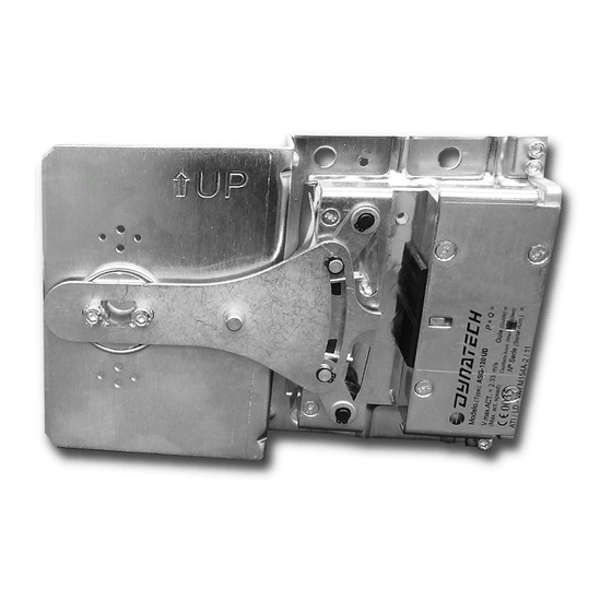
Each pair of safety gears supplied is factory tared according to the required conditions of use: Total mass
(P+Q) and guide rails' thickness. These features are indelibly displayed, along with the standardisation
password and serial number; on the protection plates on top of the safety gear boxes (see section 2.1).
It is strictly forbidden:
a) To combine and assemble safety gear boxes with different serial numbers.
b) To use a pair of safety gears for installations with characteristics different from those indicated on that
pair of safety gears' protection plates.
c) To handle any of the safety gear's components.
DYNATECH DYNAMICS & TECHNOLOGY, S.L. cannot be held responsible for the damage caused due to
the non-observance of any of these general instructions.
2 SAFETY GEAR IDENTIFICATION AND CHARACTERISATION
2.1 IDENTIFICATION
1
EU type examination certificate number
2
Safety gear type
3
Safety gear model
4
Safety gears'maximum tripping speed (m/s)
5
Total load (Kg)
6
Guide rail thickness (mm)
2.2 SAFETY GEAR'S FEATURES AND USE
a) The guide rails to be used should be cold drawn. Allowable tolerances for guide rail thickness should
be within the limits set by the standard: ISO 7465:2007.
b) For lubricated guide rails, the recommended lubricating oil is the type used for machines according to
ISO VG 150, although other viscosities within the margins established in ISO-VG may be accepted.
c) This safety gear can be used up to a maximum tripping speed of 2 m/s.
d) Allowable guide rail thicknesses: 5 – 16 mm.
e) Guide rail's braking surface equal to or more than 25mm.
2.3 RANGE OF USE
Please find below the standard P+Q table. The rated values are displayed in bold in the middle row. The safety
gears, when supplied, are set to the default rated value; however, they can be used in installations with P+Q
values within the upper and lower limits.
Cod : DYN 07.01.10
SAFETY GEAR IDENTIFICATION LABEL
7
8
9
10
11
12
Figure 1: Safety gear identification
Guide rail type
Safety gear serial number
Dynatech address
Quality assurance CE marking and notified body
number
Marking for market access to member states of the
Customs Union
QR product traceability code
3
