Gallien-Krueger 200MV Instrukcja obsługi - Strona 2
Przeglądaj online lub pobierz pdf Instrukcja obsługi dla Wzmacniacz Gallien-Krueger 200MV. Gallien-Krueger 200MV 6 stron.
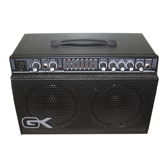
Operating Instructions 200MV
Your new G-K vocal monitor represents the very latest advances
technology has to offer. It was designed to give you full control of your
voice over other voices and instruments in the monitor mix without
affecting the mix or anyone else's monitors. With level, bass and treble
controls for the auxiliary in (monitor send from PA), built-in echo and a
7-band graphic equalizer all on the 200MV, the user can not only do his
own personal monitor mix but can also cut out any unwanted monitor
feedback again without affecting anyone else.
The 200MV can also be used as a kind of "Mini PA" for the one man
show situation. The auxiliary inputs on the rear panel can be used for
drum machines or bass line machines while the two regular inputs on
the front panel can be used for vocals and a guitar or keyboards.The
200MV can be used in many different monitoring and recording
situations (see sample setups) depending on your needs. A careful
examination of this manual will help you to get the most from your new unit.
(1) Channel 1. Balanced input
This jack accepts a 3 conductor microphone cable and has a detent to
hold the cable firmly in place. It is designed for use with microphones
or other low impedance, balanced inputs. It can also provide +15V
phantom power if needed for condenser mics. This can be turned on by
a switch located under top cover near the jack.
(2) -10dB Pad
This switch provides 10dB attenuation of the input signal if the signal is
too "hot"(ie, active electronics etc.). A signal that is too "hot" will cause
distortion in the unit even at low volumes.
(3) Channel 1. Level Control
This provides control of the signal coming in the balanced input jack. It
controls the level going to the internal amplifier as well as the level
going out the 'line out' jack (#16) and also the level going out the
balanced output jack (#17)(when switch #18 is in). It does not affect the
level going out the CH. 1. Direct jack (#19).
(4) Channel 2. Input
This jack accepts a 1/4'' phone plug and can be driven by high or low
impedance microphones or instruments such as guitars, electronic
drums, electronic keyboards, etc.
(5) Channel 2. Level
This controls the level going into CH. 2 as knob #3 did for the CH. 1
input. It also does not affect the level going out the Ch. 2 direct when
switch #18 is left out.
(6) Peak LED
This is a dual function LED. When the individual channel levels are
down all the way, this acts as a clipping indicator. If a signal is too
"hot", the LED will light even with the levels down. This indicates that
the input signal must be brought down to a useable level before it goes
into the amplifier. This can be done by pushing in the -10dB pad(#2) or
by turning down the instruments volume. This LED also acts as a peak
detector - lighting when there is only 10dB of headroom remaining
before clipping occurs.
(7) 7-Band Graphic Equalizer
This provides up to ±12dB control of seven frequency bands over a
nearly eight octave range. This is a very useful tool for eliminating
feedback by reducing the gain in the problem frequency range. It is also
useful for enhancing certain frequencies in vocals and other acoustic
and electric instruments. It affects the signal going to the internal
amplifier and to the 'line out'.
(8) Echo Mix Control
This provides control over the amount of echo present in the internal
amplifier and in the 'line out' signal. The amount of echo can range from
none at all, to a very subtle doubling, to a very heavy reverberation.
(9,10,11) Auxiliary Level. Bass and Treble Controls
These control the level and tone of the signals coming in the AUX. 1
and 2 jacks (#14) to go through the internal power amplifier. They do
not affect what goes out the AUX. Out. (#15).
(12) Master Volume Control
This is the main control for what goes to the internal amplifier (as well
as to the headphones)from CH. 1, CH. 2, and AUX. 1 and 2. (#14).
(12) Headphone Jack
This jack accepts a 1/4'' stereo phone plug (do not use a plug that is not
stereo) for the use of stereo headphones. The signal sent out of this jack
is the same as that being delivered to the speakers but at a lower level.
(13) Auxiliary In 1&2
These jacks accept 1/4'' phone plugs and can be driven by sources such
as a 'PA' mixing board (monitor send), a drum machine, an electric
guitar (with effects or an active preamp), another GK 200MV, a stereo
cassette deck, etc. The two inputs are summed internally and are
controlled by the front panel controls (#9,10,11). Note : AUX. 1 should
be used when only one AUX. Input is required.
(14) Auxiliary Out Jack
This jack puts out the sum of AUX. In 1&2 (#14) at unity gain (same
level). It is not affected by any of the front panel controls. If you have
a monitor send from a 'PA' board going into the AUX. In (#14), you can
use this jack to 'daisy chain' to other 200MVs or monitoring devices so
everyone in the 'chain' gets the same signal.
(15) Line Out Jack
The line out jack sends out the signals from CH. 1&2 (#1,4) post level
controls, EQ and Echo. This signal is the same as what is heard in the
internal amplifier minus the AUX. In (#14). This can be used for over-
dubbing in a home recording situation to record just the voice or
instrument from CH. 1&2 (#1,4) while listening to prerecorded music
from the AUX. In. (#14).
(17,18) Balanced Output/Switch Combination
This is a dual purpose output jack. With the switch in the 'out' position
the output is just a balanced output of what is going in the CH> 2 (#4)
input times a gain of 5. This is not affected by the CH. 2 level control
(#5). When the switch is pushed in, the output becomes a balanced ver-
sion of exactly what is on line out. Thus it carries both CH> 1 and CH.
2, which are controlled by their respective level controls, with EQ and
Echo. This control allows special equalization and Echo to be added to
the vocals or instruments before they are sent to the main mixing board.
(19) Channel 1 Direct
This jack provides the same signal that is being fed into the CH. 1 input
(#1). It is not affected by the level control (#3), however, it is affected
by the -10dB pad (#2). This output should go into a true balanced input
at the other end.
(20) Internal Speaker Switch
The internal speakers are on when this switch is in and can be turned off
for private headphone listening or in order to send all the internal power
to an external speaker load.
(21) External Speaker Jack
This jack accepts a 1/4'' phone plug and can send 100W RMS to 4 OHM
speaker load if the internal speakers are turned off or 50W RMS to an 8
OHM speaker load with the internal speakers on.
Note : A 4 OHM load should not be connected unless the internal
speakers are off or the amplifier may fail.