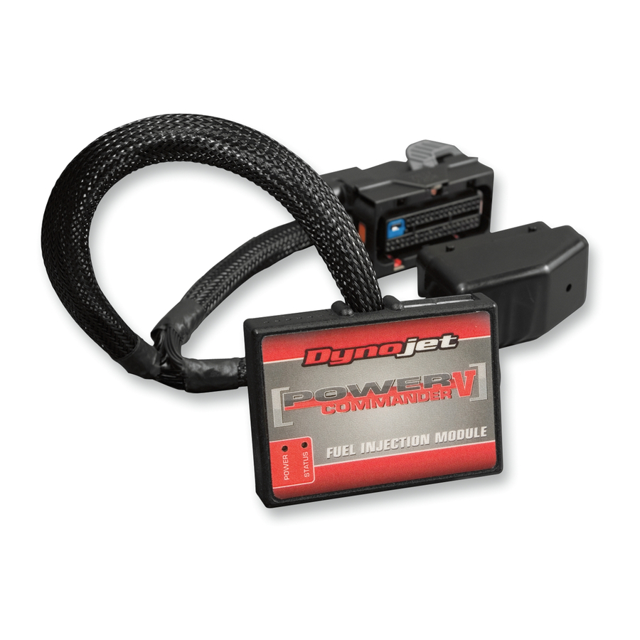
Dynojet Power commander V Instrukcje instalacji - Strona 5
Przeglądaj online lub pobierz pdf Instrukcje instalacji dla Elektronika samochodowa Dynojet Power commander V. Dynojet Power commander V 5 stron. 2017-2018 polaris scrambler 1000, 2017-2018 polaris sportsman 1000
Również dla Dynojet Power commander V: Instrukcja instalacji (6 strony), Instrukcja instalacji (9 strony), Instrukcja instalacji (7 strony), Instrukcje instalacji (4 strony), Instrukcje instalacji (5 strony), Instrukcje instalacji (4 strony), Instrukcje instalacji (5 strony), Instrukcje instalacji (4 strony), Instrukcje instalacji (5 strony), Instrukcja instalacji (6 strony), Instrukcja instalacji (6 strony), Instrukcje instalacji (5 strony), Instrukcja instalacji (6 strony), Instrukcje instalacji (5 strony), Instrukcja instalacji (6 strony), Instrukcje instalacji (5 strony), Instrukcje instalacji (5 strony), Instrukcja instalacji (7 strony), Instrukcje instalacji (5 strony), Instrukcje instalacji (4 strony), Instrukcja instalacji (6 strony), Instrukcje instalacji (4 strony), Instrukcje instalacji (5 strony), Instrukcja instalacji (6 strony), Instrukcja instalacji (8 strony), Instrukcje instalacji (4 strony), Instrukcja instalacji (7 strony), Instrukcja instalacji (6 strony), Instrukcja instalacji (8 strony), Instrukcje instalacji (4 strony), Instrukcja instalacji (6 strony), Instrukcje instalacji (4 strony), Instrukcje instalacji (4 strony), Instrukcja instalacji (6 strony), Instrukcje instalacji (5 strony), Instrukcja instalacji (6 strony), Instrukcja instalacji (6 strony), Instrukcja instalacji (6 strony), Instrukcja instalacji (7 strony), Instrukcja instalacji (6 strony), Instrukcje instalacji (5 strony), Instrukcja instalacji (5 strony), Instrukcja instalacji (6 strony), Instrukcje instalacji i podręczniki użytkownika (8 strony), Instrukcje instalacji i podręczniki użytkownika (6 strony), Instrukcja instalacji (4 strony), Instrukcja instalacji (7 strony), Instrukcja instalacji (6 strony), Instrukcja instalacji (6 strony), Instrukcja instalacji (6 strony), Instrukcje instalacji (5 strony), Instrukcje instalacji (5 strony), Instrukcja instalacji (6 strony), Instrukcja instalacji (8 strony), Instrukcja instalacji (5 strony), Instrukcja instalacji (9 strony), Instrukcja instalacji (4 strony), Instrukcje instalacji (4 strony), Instrukcja instalacji (6 strony), Instrukcja instalacji (7 strony), Instrukcja instalacji (7 strony), Instrukcje instalacji (5 strony), Instrukcja instalacji (7 strony), Instrukcje instalacji (4 strony), Instrukcje instalacji (4 strony), Instrukcje instalacji (5 strony), Instrukcje instalacji (5 strony), Instrukcja instalacji (6 strony), Instrukcje instalacji (5 strony), Instrukcja instalacji (5 strony), Instrukcja instalacji (6 strony), Instrukcja instalacji (7 strony), Instrukcje instalacji (4 strony), Instrukcja instalacji (7 strony), Instrukcje instalacji (5 strony), Instrukcje instalacji (4 strony), Instrukcje instalacji (4 strony), Instrukcje instalacji (4 strony), Instrukcje instalacji (5 strony), Instrukcje instalacji (5 strony), Instrukcje instalacji (5 strony), Instrukcje instalacji (4 strony), Instrukcje instalacji (5 strony), Instrukcje instalacji (4 strony), Instrukcje instalacji (4 strony), Instrukcja instalacji (6 strony), Instrukcje instalacji (4 strony), Instrukcje instalacji (5 strony), Instrukcja instalacji (7 strony), Instrukcje instalacji (4 strony), Instrukcje instalacji (5 strony), Instrukcje instalacji (5 strony), Instrukcja instalacji (6 strony), Instrukcje instalacji (4 strony), Instrukcja instalacji (7 strony), Instrukcja instalacji (6 strony), Instrukcje instalacji (4 strony), Instrukcja instalacji (6 strony)

