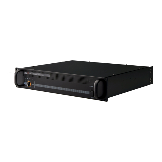
Majorcom: DPS-240S Podręcznik użytkownika - Strona 5
Przeglądaj online lub pobierz pdf Podręcznik użytkownika dla Wzmacniacz Majorcom: DPS-240S. Majorcom: DPS-240S 9 stron.

8
DPS-240S/360S/480S/720S
Rear Panel
Rear Panel
1
2
1. AC INPUT
Connect the power cable which is supplied with the unit. Do not bend, pull, twist, heat and cut by force. It
may cause electric shock.
2. DC INPUT
this is emergency DC terminal (DC 24V). When something happens to AC power, DC power automatically
operates. Input provides power to the device regardless of power switch.
※ Please check voltage and +, - polarity.
3. AC POWER REMOTE
this terminal allows the amplifier to be turned on or off from a distance or other device.
4. AIR VENTS
Air circulation vents to prevent the device from overheating. Please be careful not to block the front/back of
the vents.
5. PRIORITY INPUT AND CONTACT CLOSURE
each amplifier module has 2 audio inputs. the PgM input and PRIoRItY input. PgM input is interrupted and
over ridden by the PRIoRItY input when a contact closure is received on the PRI select terminal. this is Ideal
for emergency message broadcasting applications. Please refer to the following picture about the suitable
cables.
PRIORITY
SW
INPUT
+ -
N.C
1
G
COM
Usermanual V1.1
56, chemin
de la Flambère ·
F a x 3 3 ( 0 ) 5 6 1 3 1 8 7 7 3 · [email protected] ·
7
5
6
PRIORITY
PRIORITY
VOLUME
SW
INPUT
+ -
N.C
1
COM
G
MIN
MAX
OUTPUT
CH 1
N.C
AC POWER
PGM INPUT
OUTPUT
REMOTE
VOLTAGE
+ -
G
100V
70V
3
4
8
}
G
-
INPUT
+
}
COM
SW
1
31300 Toulouse ·
FRANCE · T é l . 3 3 ( 0 ) 5 6 1 3 1 8 6 8 7
www.majorcom.fr
6. PRIORITY VOLUME CONTROL
It is a volume control of PRIoRItY INPUt signal. this control can adjust PRIoRItY INPUt signal used as
emergency broadcasting. turn clockwise to turn the signal level and counterclockwise to lower the signal
level.
※ It is mainly for priority broadcasting so, don't make the VolUMe level too low.
7. OUTPUT TERMINAL
Speaker output terminal. Before connecting speakers to the unit, be sure to disconnect the AC power cable.
Make certain that the total impedance is not less than the rated impedance indicated.
9
※ Caution:
1. Make sure that the total impedance does not equal or less than the rated impedance.
2. Do not connects a speaker has lower impedance than rated impedance, it may cause the problem to unit.
3. Do not put the speaker cable close to input signal cable.
8. OUTPUT VOLTAGE SELECTOR SWITCH
this two-position switch is used to select a output voltage. (100V / 70V)
DPS-240S/360S/480S/720S
OUTPUT
CH 1
N.C
10W
10W
Speaker output
Speaker Impedance
240W
360W
480W
720W
56, chemin
de la Flambère ·
31300 Toulouse ·
F a x 3 3 ( 0 ) 5 6 1 3 1 8 7 7 3 · [email protected] ·
9
. . . .
10W
10W
100V / 41.7Ω
70V / 20.4Ω
100V / 27.8Ω
70V / 13.6Ω
100V / 20.8Ω
70V / 10.2Ω
100V / 13.9Ω
70V / 6.8Ω
Usermanual V1.1
FRANCE · T é l . 3 3 ( 0 ) 5 6 1 3 1 8 6 8 7
www.majorcom.fr
