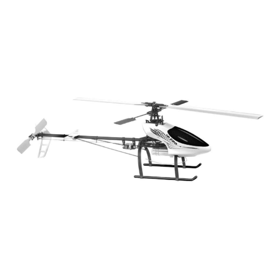
Century Helicopter Products Hummingbird Elite 3D Pro Instrukcja obsługi - Strona 4
Przeglądaj online lub pobierz pdf Instrukcja obsługi dla Zabawka Century Helicopter Products Hummingbird Elite 3D Pro. Century Helicopter Products Hummingbird Elite 3D Pro 10 stron.
Również dla Century Helicopter Products Hummingbird Elite 3D Pro: Instrukcja montażu i obsługi (12 strony)

Section 3
Speed Control Connection
Aileron, Elevator & Pitch Servo Connection
6 5 4 3 2 1
Channels
Ch#1
Aileron
Elevator
Rudder Servo & Gyro Connections
1 2 3 4 5 6
Channels
Motor Connection
The blades on the helicopter should spin clockwise. If the
motor is turning the wrong way, switch two of the motor
wires to reverse the rotation.
Section 4
AILERON, ELEVATOR AND PITCH SERVOS -
TEST EVERYTHING FIRST!
1 & 2. Trim both servo mounting flanges from each servo.
3. Before installing you will need to remove the pushrods from the
swashplate of the helicopter. Keep the pushrods on the side until
you install the correct servo arms (next subsection).
Servo Arm Retaining Screw
Servo Lead
IMPORTANT: Do not modify the rudder servo
w/Connector
SERVO ARMS AND HORNS FOR THE 3D PRO
1. A long half arm may have to be created by cut-
ting a full or cross arm.
2. After testing the radio equipment the servos
will be in their center position. Remove the servo
retaining screw and servo wheel. Replace the
wheel with one of the long half arms. See section
3 for the final positions for your version.
3. Some servo arms require widening the hole in the arm in order for them to accept the
Hummingbird's pushrods using a #55 drill bit [1.34mm or 0.052"].
4
Connection And Diagnostics For The
TESTING AND PREPARATION OF RADIO EQUIPMENT
Ch#2
Ch#6
Pitch (CP)
The gyro helps the
helicopter maintain
heading. Without the
gyro the helicopter
might spin out of
control.
Channel numbers
(DO NOT MODIFY THE RUDDER SERVO)
The Servo
Servo Arm/Horn/Wheel
Servo Output Shaft
Servo Mounting Flange
Servo Case
1
Electronic Components
PLEASE DON'T SKIP THIS SECTION!!!!
IMPORTANT:
!
Before modifying or installing any radio gear, please take
All connections shown
a few minutes to test everything as shown. Time spent
in this manual work for
becoming familiar with the equipment and testing all the
Futaba & Hitec radio
components can prevent difficulty.
systems. If you have
any other radio system
please consult your radio
1. Install the crystals into the transmitter and receiver. Be
instructions for channel
certain that the channel frequency matches.
numbering. (some
equipment may differ in
2. Note that all electronics plug into the receiver with
appearance.)
Positive negative and
the wires as pictured (orange wire faces receiver label).
signal pins for the
Follow the diagram for each electronic connection. Once
receiver should be
the electronics system is connected and the transmitter
marked on the casing
is turned on, follow this step-by-step process to check
of the receiver or in the
manual for the receiver.
your equipment.
1
2
Signal, positive
must match
& negative are
connected correctly
Servo Basics
3
BAD
STEP-BY-STEP COMPONENT TEST
1. Turn on the transmitter
3. Move the aileron,
elevator pitch and
- Is the transmitter
rudder channels to
functioning normally?
make sure the servos
2. Plug the Battery into
work. With the gyro
your Speed controller.
connected properly
Wait for the speed
the rudder servo
should move when
control and gyro to
turning the helicopter.
initialize before moving
the helicopter.
2
1
GOOD
3
2
Carefully
remove ball
link from
swashplate
ball. Too
much force
may break
the plastic
balls.
10-12mm
