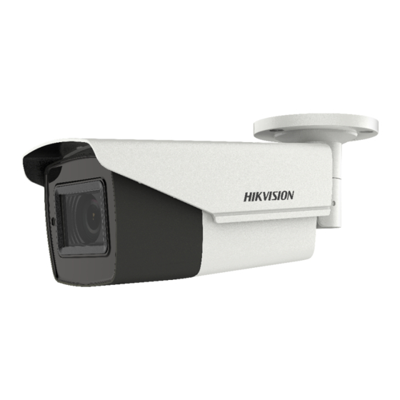
HIKVISION TurboHD DS-2CE16H0T-AIT3ZF Podręcznik użytkownika - Strona 6
Przeglądaj online lub pobierz pdf Podręcznik użytkownika dla Kamera bezpieczeństwa HIKVISION TurboHD DS-2CE16H0T-AIT3ZF. HIKVISION TurboHD DS-2CE16H0T-AIT3ZF 15 stron. Bullet and turret camera
Również dla HIKVISION TurboHD DS-2CE16H0T-AIT3ZF: Podręcznik użytkownika (16 strony)

6. Power on the camera to check whether the image
on the monitor is gotten from the optimum angle. If
not, adjust the surveillance angle.
1) Loosen the No.① adjusting screw to adjust the
pan position [0° to 360°]. Tighten the No.①
adjusting screw.
2) Loosen the No.② adjusting screw to adjust the
tilting position [0° to 90°]. Tighten the No.②
adjusting screw.
3) Loosen the No.③ adjusting screw to adjust the
rotation position [0° to 360°]. Tighten the No.③
adjusting screw.
2.1.2 Ceiling Mounting with
Before you start:
You need to purchase a junction box separately.
Both wall mounting and ceiling mounting are suitable
for the bullet camera. Ceiling mounting will be taken
as an example in this section. And you can take steps
of ceiling mounting as a reference for wall mounting.
Steps:
1. Paste the junction box's drill template on the ceiling.
2. Drill screw holes and the cable hole (optional) in the
ceiling according to the holes of the drill template.
Note:
Drill the cable hole, when adopting ceiling outlet to
route the cable.
3. Take apart the junction box, and align the screw
holes of the bullet camera with those on the
junction box's cover.
4. Fix the camera on the junction box's cover.
Figure 2-4 Fix the Camera with the Gang Box
5. Attach the junction box's body to the ceiling by
aligning the screw holes of the junction box.
6. Secure the junction box's body with supplied screws
on the ceiling.
Figure 2-3 3-axis Adjustment
Junction Box
