1
2
3
4
5
6
7
8
9
10
11
Atención:
Debido a un dispositivo de seguridad adicional, los 4 interruptores de la emisora
tienen que estar en posición "Off" (apagados) al encender la emisora. Si este no
fuera el caso, aparecerá un aviso en la pantalla y además escuchará un sonido de
advertencia, hasta que todos los interruptores se encuentren en la posición correcta.
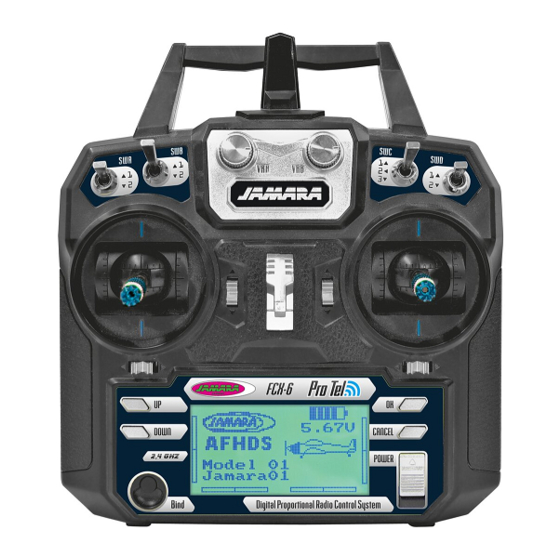
ES - Descripción gas derecha
1
Antena 2,4 GHz
2
Botón VRB (Programable)
3
Interruptor B (Programable)
4
Interruptor A (Programable)
12
5
Modo 1 = Mando cabeceo/Cola
Modo 3 = Mando cabeceo/alabeo
6
Trim de cabeceo
13
7
Modo 1 = Trim de alabeo
Modo 3 = Trim de cola
14
8
Botón arriba
9
Botón abajo
10 LCD
15
11 Botón de encendido
12 Botón VAA (Programable)
13 Interruptor C (Programable)
14 Interruptor D (Programable)
16
15 Ojal para correa
16 Modo 1 = Mando de paso/alabeo
17
Modo 3 = Mando de paso/cola
17 Trimmung Gas
18
18 Modo 1 = Trim de cola
19
Modo 3 = Trim de alabeo
19 Botón confi rmación (Enter)
20
20 Exit/Atrás botón
21 Interruptor On/Off
21
GB - Defi nition of key funktions throttle right
1
2,4 GHz Antenna
2
Rotary poteniometer VRB (free programmable)
3
Switch B (free programmable)
4
Switch A (free programmable)
5
Mode 1 = Elevator/Rudder stick
Mode 3 = Elevator/Aileron stick
6
Elevator Trim
7
Mode 1 = Aileron Trim
Mode 3 = Rudder Trim
8
Key up
9
Key down
10 LCD Display
11 Bonding button
12 Rotary poteniometer VAA (free programmable)
13 Switch C (free programmable)
14 Switch D (free programmable)
15 Hook
16 Mode 1 = Throttle/Aileron stick
Mode 3 = Throttle/Rudder stick
17 Throttle Trim
18 Mode 1 = Rudder Trim
Mode 3 = Aileron Trim
19 Enter button
20 Exit / Back button
21 Power switch
Warning:
For your safely, the 4 switches of the transmitter must be in their „off" postition and
throttle stick must be the lowest position when turning the transmitter on. If not, a war-
ning screen will be displayed until all switches are in the right position.
5