CORNING EDGE8-02U Instalacja i testowanie - Strona 10
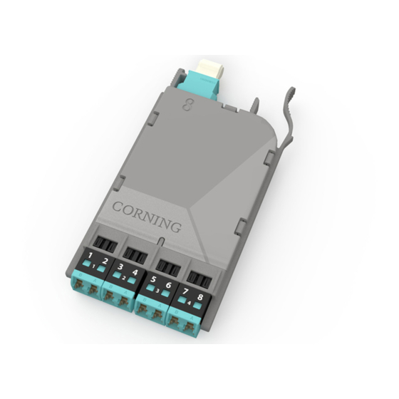
Przeglądaj online lub pobierz pdf Instalacja i testowanie dla Jednostka sterująca CORNING EDGE8-02U. CORNING EDGE8-02U 13 stron. Tap module
Również dla CORNING EDGE8-02U: Instalacja i testowanie (8 strony)
9.3.
Table 4 provides a complete guide to the test sequence with a light source and test harness at
the front-mounted TAP MTP connector and a meter and test harness at the front-mounted TAP MTP
connector of the system shown in Figure 14.
Source LC Position at LIVE port test
9.4
To begin testing the TAP portion of the MTP Tap module from the "A" LIVE Port harness to the
module TAP port test harness (Figure 14):
Step 1:
Install the Light Source/RJ1 LC connector adapter onto the LC number 2
connector of a test harness plugged into the LIVE port of the MTP Tap module.
Step 2:
Install RJ2's LC connector adapter onto the LC number 1 connector of a harness
plugged into the TAP port of the MTP Tap module.
multimode only
Do NOT
disconnect
Light
Source
Do NOT
0.00 dB
disconnect
M1
HPA-1004-EDGE8
STANDARD RECOMMENDED PROCEDURE 003-139-AEN | ISSUE 1 | JANUARy 2017 | PAGE 10 OF 13
harness "A"
A-2
A-4
A-6
A-8
Table 4: Test Sequence
LC #2
"A"
RJ1
and
adapter
LC #1
RJ2
and
adapter
LC #8
Meter # 1 and TAP port test
harness at LC #
LC #8
port test harness
TAP
port test harness
1
3
5
7
LIVE
EDGE8 Tap Module "A"
Figure 14