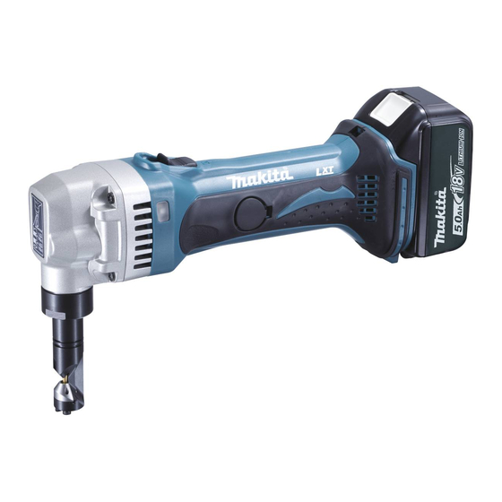
Makita BJN160 Instrukcja obsługi - Strona 6
Przeglądaj online lub pobierz pdf Instrukcja obsługi dla Elektronarzędzie Makita BJN160. Makita BJN160 13 stron. Cordless nibbler
Również dla Makita BJN160: Instrukcja obsługi (13 strony), Instrukcja obsługi (11 strony), Informacje techniczne (8 strony), Instrukcja obsługi (12 strony)

IMPORTANT SAFETY INSTRUCTIONS
FOR BATTERY CARTRIDGE
1.
Before using battery cartridge, read all instruc-
tions and cautionary markings on (1) battery
charger, (2) battery, and (3) product using bat-
tery.
2.
Do not disassemble battery cartridge.
3.
If operating time has become excessively
shorter, stop operating immediately. It may
result in a risk of overheating, possible burns
and even an explosion.
4.
If electrolyte gets into your eyes, rinse them out
with clear water and seek medical attention right
away. It may result in loss of your eyesight.
5.
Do not short the battery cartridge:
(1) Do not touch the terminals with any conduc-
tive material.
(2) Avoid storing battery cartridge in a con-
tainer with other metal objects such as nails,
coins, etc.
(3) Do not expose battery cartridge to water or
rain.
A battery short can cause a large current flow,
overheating, possible burns and even a break-
down.
6.
Do not store the tool and battery cartridge in
locations where the temperature may reach or
exceed 50°C (122°F).
7.
Do not incinerate the battery cartridge even if it
is severely damaged or is completely worn out.
The battery cartridge can explode in a fire.
8.
Be careful not to drop or strike battery.
9.
Do not use a damaged battery.
SAVE THESE INSTRUCTIONS.
Tips for maintaining maximum battery life
1.
Charge the battery cartridge before completely
discharged.
Always stop tool operation and charge the bat-
tery cartridge when you notice less tool power.
2.
Never recharge a fully charged battery cartridge.
Overcharging shortens the battery service life.
3.
Charge the battery cartridge with room tempera-
ture at 10°C – 40°C (50°F – 104°F). Let a hot bat-
tery cartridge cool down before charging it.
4.
Charge the battery cartridge once in every six
months if you do not use it for a long period of
time.
FUNCTIONAL DESCRIPTION
CAUTION:
• Always be sure that the tool is switched off and the bat-
tery cartridge is removed before adjusting or checking
function on the tool.
6
Installing or removing battery cartridge (Fig. 1)
ENC007-7
CAUTION:
• Always switch off the tool before installing or removing
of the battery cartridge.
• Hold the tool and the battery cartridge firmly when
installing or removing battery cartridge. Failure to
hold the tool and the battery cartridge firmly may cause
them to slip off your hands and result in damage to the
tool and battery cartridge and a personal injury.
To remove the battery cartridge, slide it from the tool
while sliding the button on the front of the cartridge.
To install the battery cartridge, align the tongue on the
battery cartridge with the groove in the housing and slip it
into place. Insert it all the way until it locks in place with a
little click. If you can see the red indicator on the upper
side of the button, it is not locked completely.
CAUTION:
• Always install the battery cartridge fully until the red
indicator cannot be seen. If not, it may accidentally fall
out of the tool, causing injury to you or someone
around you.
• Do not install the battery cartridge forcibly. If the car-
tridge does not slide in easily, it is not being inserted
correctly.
Changing the die position (Fig. 2)
The die holder position can be changed 360°. To change
it, proceed as follows.
1. Loosen the lock nut with the wrench provided.
2. Pull the die holder slightly and turn it to the desired
position for operation.
3. Tighten the lock nut to secure the die holder in the
desired position.
There are four positive stops at 90° each: 0°, 90° left and
right and 180°. To position the die to any of these positive
stops:
4. Loosen the lock nut with the wrench provided.
5. Pull the die holder slightly and depress lightly while
turning it to the desired position. The die holder will
lock into one of the positive stop positions as desired.
6. Turn the die holder slightly to make sure that it is posi-
tively locked into position.
7. Tighten the lock nut to secure the die holder.
Permissible cutting thickness (Fig. 3)
The thickness of material to be cut depends upon the
tensile strength of the material itself. The groove on the
die holder acts as a thickness gauge for allowable cutting
thickness. Do not attempt to cut any material which will
not fit into this groove.
Cutting line
The notch in the die holder indicates your cutting line. Its
width is equal to the cutting width. Align the notch to the
cutting line on the workpiece when cutting.
Switch action (Fig. 4)
CAUTION:
• Before inserting the battery cartridge into the tool,
always check to see that the slide switch actuates
properly and returns to the "OFF" position when the
rear of the slide switch is depressed.
• Switch can be locked in "ON" position for ease of oper-
ator comfort during extended use. Apply caution when
locking tool in "ON" position and maintain firm grasp on
tool.
