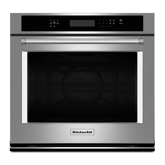
KitchenAid KEBS209E Instrukcja instalacji - Strona 2
Przeglądaj online lub pobierz pdf Instrukcja instalacji dla Piekarnik KitchenAid KEBS209E. KitchenAid KEBS209E 16 stron. 27" (68.6 cm) and 30" (76.2 cm) electric single and double built-in oven

We have provided many important safety messages in this manual and on your appliance. Always read and obey all safety
messages.
This is the safety alert symbol.
This symbol alerts you to potential hazards that can kill or hurt you and others.
All safety messages will follow the safety alert symbol and either the word "DANGER" or "WARNING."
These words mean:
DANGER
WARNING
All safety messages will tell you what the potential hazard is, tell you how to reduce the chance of injury, and tell you what can
happen if the instructions are not followed.
Gather the required tools and parts before starting installation.
Read and follow the instructions provided with any tools listed
here.
Tools Needed
Phillips screwdriver
■
Measuring tape
■
Hand or electric drill (for wall cabinet installations)
■
1" (2.5 cm) drill bit (for wall cabinet installations)
■
Level
■
Flat-blade screwdriver
■
Parts Needed
UL listed or CSA approved conduit connector
■
UL listed wire connectors
■
Warming Drawer Deflector Kit (for ovens installed above a
■
warming drawer)
Order Part Number W10510613 for white 27" (68.6 cm) kit
Order Part Number W10531009 for black 27" (68.6 cm) kit
Order Part Number W10536338 for stainless steel 27"
(68.6 cm) kit
Order Part Number W10510614 for white 30" (76.2 cm) kit
Order Part Number W10531010 for black 30" (76.2 cm) kit
Order Part Number W10536339 for stainless steel 30"
(76.2 cm) kit
Order Part Number W10727416A for stainless steel/black 30"
(76.2 cm) kit
To order, see the "Assistance or Service" section of the Use
and Care Guide.
2
BUILT-IN OVEN SAFETY
Your safety and the safety of others are very important.
INSTALLATION REQUIREMENTS
You can be killed or seriously injured if you don't immediately
follow instructions.
You can be killed or seriously injured if you don't follow
instructions.
Tools and Parts
Flush Installation Kit (for Single and Double installed at flush
■
installation)
Order Part Number W10752684A for white 27" (68.6 cm) kit
Order Part Number W10752685A for black 27" (68.6 cm) kit
Order Part Number W10752686A for stainless steel 27"
(68.6 cm) kit
Order Part Number W10752680A for white 30" (76.2 cm) kit
Order Part Number W10752681A for black 30" (76.2 cm) kit
Order Part Number W10752683A for stainless steel 30"
(76.2 cm) kit
Order Part Number W10752682A for black/stainless steel 30"
(76.2 cm) kit
To order, see the "Assistance or Service" section of the Use
and Care Guide.
Parts Supplied
#8-14 x 1" screws - single ovens (2), double ovens (4)
■
#8-18 x ³⁄₈" screws - bottom vent (2)
■
#8-18 x ¹⁄₄" screws - bottom vent trim (4)
■
#8-18 x ³⁄₈" screws - double oven feet (4)
■
Bottom vent
■
Bottom vent trim
■
Rear feet - double oven (2)
■
Front feet - double oven (2)
■
Foam strip - single oven*
■
Check local codes. Check existing electrical supply. See
"Electrical Requirements."
It is recommended that all electrical connections be made by a
licensed, qualified electrical installer.
*Foam strip not included with double oven.
