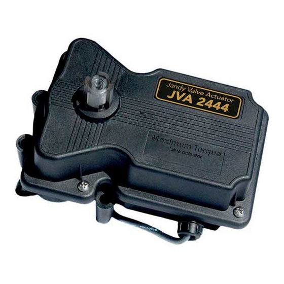
Jandy JVA 2444 Pro Series Instrukcja instalacji i obsługi - Strona 11
Przeglądaj online lub pobierz pdf Instrukcja instalacji i obsługi dla Kontroler Jandy JVA 2444 Pro Series. Jandy JVA 2444 Pro Series 16 stron.

Jandy
Section 7. Wiring Diagrams
7.1
JVA Wiring Schematic 2444
WARNING
Disconnect power to the system at the main circuit
breaker before servicing to avoid risk of electric shock
which can result in property damage, severe injury
or death. All wiring must be done in accordance with
the National Electrical Code
In Canada, all wiring must be done in accordance
with the Canadian Electrical Code (CSA C22.1). All
applicable local installation codes and regulations
must be followed.
CAUTION
To avoid damage to the equipment and minimize
risk of injury, use a properly sized, listed Class 2
transformer for connection to the power supply.
7.2
JVA's with Toggle Switch
This diagram is for two (2) JVA 2444s.
To operate more JVA's, additional poles and a higher
amperage fuse are needed. Do not double lug the JVA
switch leg wires (red and white wires).
Secondary
(24 VAC)
Double Pole/
2 amp
Double Throw
fuse
Toggle Switch
Normally Closed
Common
Normally Open
BLACK
RED
WHITE
OFF
* Transformer must be sized for the number of JVA's.
Each JVA requires .75 amp. at 24 VAC.
Pro Series Valve Actuator
®
(NEC
), NFPA-70.
®
®
Transformer*
Primary
(120 VAC)
RED
WHITE
BLACK
|
Installation and Operation Manual
Common
Bottom Cam
Motor
Connector
to PCB
Header
Black
Red
White
7.3
JVA's with Time Clock
This diagram is for a single JVA 2444.
To operate more JVA's, additional poles and a higher
amperage fuse are needed. Do not double lug the JVA
switch leg wires (red and white wires).
120 VAC
Normally Closed
Common
Normally Open
Single Pole/
OFF
Double Throw
Relay
Coil Voltage: 120 VAC
* Transformer must be sized for the number of JVA's.
Each JVA requires .75 amp. at 24 VAC.
ENGLISH
Left
Right
Micro switch
Micro switch
NO
NC
Red
White
Black
Black
Wiring to Toggle
Switch Underneath
Circuit Board
Red
Black
White
PCB Header for Motor Wiring
Transformer*
Secondary
Primary
(24 VAC)
(120 VAC)
1 amp
fuse
RED
WHITE
BLACK
Page 11
Common
NO
NC
Top Cam
Motor
Connector
to PCB
Header
Time
Clock
120 VAC
OFF
