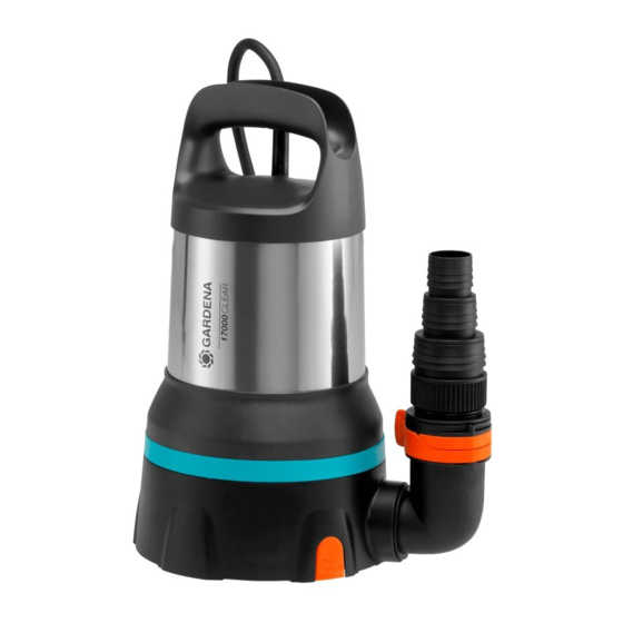
Gardena 9036 Instrukcja obsługi - Strona 5
Przeglądaj online lub pobierz pdf Instrukcja obsługi dla Pompa wodna Gardena 9036. Gardena 9036 17 stron. Clear water submersible pump/ dirty water submersible pump
Również dla Gardena 9036: Instrukcja obsługi (16 strony)

Large hose diameter
GARDENA Connection System /
Art. 9036 / 9044: Medium hose
diameter
Small hose diameter
When using the largest hose diameter, the pump has the
maximum delivery capacity.
Pump
Art. 9034
Small hose
25 mm (1")
diameter
Art. GARDENA
Art. 7193
Hose Clamp
Medium hose
GARDENA Connection
diameter
System G 1"
Art. GARDENA
32 mm (1 1/4") *
Hose Clamp
Art. 7194
Large hose
38 mm (1 1/2")
diameter
Art. GARDENA
Art. 7195
Hose Clamp
When using the 38 mm (1 1/2") hose, we recommend the
GARDENA Flat Hose Set Art. 5005 with 10 m hose and
hose clamp.
* For Art. 9034 an additional connection nipple
1 1/4" hoses is supplied.
To connect the hose via the connection nipple:
1. When using the large diameter hose, cut off the con-
(4)
(a)
nection nipple
at
.
2. Only for Art. 9036 / 9044: When using the medium
hose diameter, cut off the connection nipple
3. Push the hose onto the connection nipple
4. Fix the hose to the connection nipple
a GARDENA Hose Clamp.
Connect hose via the GARDENA Connection System:
With 17000 AS CLEAR / 20000 AS DIRT (Art. 9036 / 9044)
the hose cannot be connected via the connection nipple
with the GARDENA Connection System.
3. OPERATION
DANGER! Risk of physical injury!
Injury when the product starts accidentally.
v Disconnect the product from the mains before
you connect, adjust or transport the product.
To pump water:
If the pump cannot be immersed via the handle, the pump
must always be immersed via a rope. Attach the rope
by pulling it through the eyelets provided and knotting
it. Minimum immersion depth during initial operation
see 7. TECHNICAL DATA.
(a)
Cut off nipple at
[ Fig. A2 ]
(b)
Cut off nipple at
[ Fig. A3 ]
Do not cut off nipple
[ Fig. A4 ]
Art. 9036
Art. 9044
32 mm (1 1/4")
Art. 7194
38 mm (1 1/2")
Art. 7195
51 mm (2")
Art. 7196
ß
for
4a
(4)
(b)
at
.
(4)
.
(4)
e.g. with
(4)
19 mm (3/4") / 15 mm (5/8") and 13 mm (1/2") hoses can
be connected via the GARDENA Connection System.
We do not recommend hose diameters smaller than
25 mm (1"), otherwise there will be a significant reduction
in the output of the delivery rate.
Hose diameter
Pump connection
13 mm (1/2")
GARDENA Pump Connection Set
15 mm (5/8")
GARDENA Pump Connection Set
19 mm (3/4")
GARDENA Pump Connection Set
1. Cut off the connection nipple
2. Connect the hose to the connection nipple
appropriate GARDENA Connection System.
To assemble the pump connection [ Fig. A5 ]:
DANGER! Risk of physical injury!
Injured cut by the impeller.
v Operate the pump only with the elbow con-
nector.
The hose can be easily connected and disconnected using
(2)
the locking devices
on the elbow connector
With Art. 9034 / 9036 a non-return valve is supplied which
prevents water from flowing back through the hose. The
max. delivery rate is only achieved without the non-return
valve.
If only a small amount of reflux is expected, e. g. if the hose
is laid flat, we recommend dispensing with the valve due to
the better delivery and suction performance.
1. Only for Art. 9034 / 9036: Insert the non-return valve
into the pump. Observe the installation direction.
2. Screw the elbow connector
until it stops. (If the hose is to be installed horizontally,
(1)
the elbow connector
to half a turn. When using the non-return valve,
increased force is required.)
3. Screw the connection piece
(4)
nipple
.
4. Push the connection nipple
(1)
elbow connector
until it stops until it engages audibly
and visibly.
The hose is securely connected to the pump.
Take care that the pump is located where the inlet open-
ings at the suction base are not obstructed neither com-
pletely nor partly.
Stand the pump on a brick if using in a pond.
If the suction process is close to the minimum water level
at start-up, the suction process may take longer.
1. Immerse the pump.
2. Connect the pump to the mains.
The sensor is initialised and indicated by a running light.
Art. 1750
Art. 1750
Art. 1752
(4)
(b)
at
.
(4)
via the
(1)
.
(1)
clockwise into the pump
can be screwed out again up
(3)
into the connection
(4)
of the hose into the
ß
V
15
