Gardena V1 Instrukcja obsługi - Strona 3
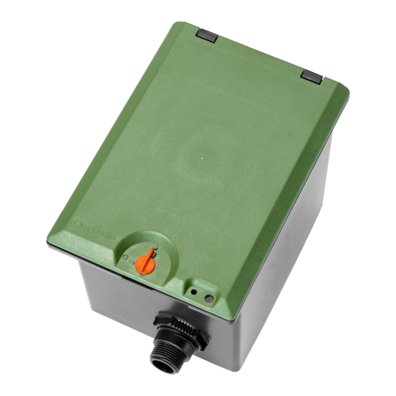
Przeglądaj online lub pobierz pdf Instrukcja obsługi dla Sprzęt do trawników i ogrodów Gardena V1. Gardena V1 6 stron. Valve box
Również dla Gardena V1: Instrukcja obsługi (10 strony), Instrukcja obsługi (11 strony), Instrukcja obsługi (9 strony)

2. For underground installation, place a layer of course gravel
approx. 20 x 30 x 10 cm
neath the valve box. This ensures proper drainage of the box.
1
3. Install the valve box with the top edge of the box at ground
level. This avoids damage when mowing the lawn.
1
Connect GARDENA connect-
You can use the GARDENA Connecting Pipe Art. No. 1580 /
3
ing pipes to valve box :
1582
and GARDENA Hose Clips Art. No. 1591
the valve box.
1. Push the nipples
6
5
6
2. Fasten the nipples
the nuts
3. Screw a tap connector
4. Push a hose clip
4
4
Tip : Place the pipe ends
2
3 4
push the ends of the pipes
5. Push the connecting pipes
secure with the hose clips
Note : You can also attach a GARDENA Connector Art. No.
2745/ 2749
connecting hard connecting pipes or other commercially avail-
6
5
6
able connecting pipes.
After connecting the pipes to the valve box, the system must be
flushed.
7
7
Flash the system :
Flushing the system after routing the pipes prevents contaminating
the valves.
1. Push the long telescopic pipe
on the outlet-side
0
2. Push the flushing pipe
3. Push the bracket
the inlet-side
The flushing pipe
5
9
8
z
4. Screw the long telescopic pipe
5 a
5. Turn on the water supply at the nipple
The system is flushed.
6. Remove the flushing pipe
12
3
3
(V 1) / 30 x 35 x 10 cm
(V 2) under-
2
to connect
5
from the inside into the box openings.
5
to the valve box from the outside using
6
.
4
5
on each nipple
.
2
3
over each pipe end
.
3
in warm water to make it easier to
3
4
onto the tap connectors
3
onto the tap connectors
2
.
7
(1 " = 25 mm / 5 /4 " = 32 mm) to the nipples
8
all the way into the nipple
5
a.
9
into the nipple on the inlet-side
0
into the elongated holes of the nipple on
5
.
9
is fixed in place.
8
onto the flushing pipe
5
.
9
.
1
Close off nipple
on inlet-side :
0
5
A
B
Assemble the
Irrigation Valve :
0
.
4
and
5
for
5
A C
Lock the box lid :
E
F
5
.
9
.
Connect Soil Moisture
Sensor or Rain Sensor
electronic (optional) :
If you connect several Irrigation Valves to one water supply, then
each pipe must be flushed separately in order to obtain an ade-
quate flushing pressure. To do this:
1. Push the short telescopic pipe
5
side
which is not to be flushed.
0
2. Push the bracket
into the elongated holes of the nipple on
5
the inlet-side
.
A
The short telescopic tube
B
3. Screw the end cap
onto the short telescopic pipe
The integrated solenoid valve only works correctly with the
Irrigation Valve connected in flow direction.
Flow direction
A
V Pay attention to the flow direction (arrows) when
assembling the Irrigation Valve
1. Push the long telescopic pipe
5
on the outlet-side
a.
2. Screw the short telescopic pipe
C
Irrigation Valve
.
The arrows on the Irrigation Valve point in the flow direction.
3. Push the short telescopic pipe
side
5
.
4. Screw the long telescopic pipe
C
Irrigation Valve
.
0
5. Push the bracket
into the elongated holes of the nipples
8
z
5 a
5
5
/
a.
The telescopic pipes
8
/
A
D
When you open the box lid
marked by the arrows on the Irrigation Valve
D
v The box lid
can be locked by turning the lever
D
The box lid
can be locked as a protection against theft.
D
F
v Overlap the holes
of the valve box and the box lid and lock
using a small padlock
– or –
D
alternatively, the lid
can be safeguarded against theft using
a sheet metal screw (4.2 x 19).
In conjunction with the programmed watering time, the moisture
level of the soil or the natural precipitation can be taken into
account for each Irrigation Valve.
When a sufficient moisture content of the soil is reached, a pro-
gramme may be interrupted or activation of a programme may
be suppressed.
A
into the nipple on the inlet-
is fixed in place.
A
.
C
.
8
all the way into the nipple
A
into the inlet side of the
A
into the nipple on the inlet-
8
into the outlet-side of the
are fixed in place.
you can see the flow direction
C
.
E
by 90°.
13
