Gardena 1254 Instrukcja obsługi - Strona 3
Przeglądaj online lub pobierz pdf Instrukcja obsługi dla System nawadniania Gardena 1254. Gardena 1254 8 stron. Valve box
Również dla Gardena 1254: Instrukcja obsługi (8 strony), Instrukcja obsługi (11 strony), Instrukcja obsługi (9 strony)

3. Assembly
Installing a
Central Filter :
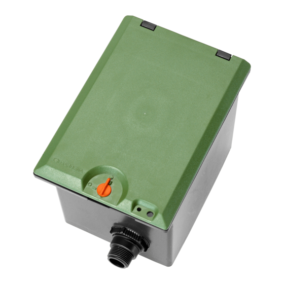
Install the Valve Box :
1
2
Connect GARDENA
connecting pipes
to valve box :
4
5
6
2
2
7
2
V3: Close open distributor
output :
9
0
8
A
We recommend installing the GARDENA Central Filter
Art. 1506 / 1510 upstream of the watering system to
protect the components of the watering system from
dirt and contamination. If you are using dirty water, a
filter must be installed upstream of the watering system.
V Grease all O-rings and metal securing clips before
assembly ! Push an O-ring over each end of the
telescopic pipe
1. Install the Valve Box
20 cm x 30 cm x 10 cm (V1) / 30 cm x 35 cm x 10 cm (V3).
This ensures proper drainage of the box.
2. Install the valve box with the top edge of the box at ground
level. This avoids damage when mowing the lawn.
When installing the Valve Box, the lid must be closed. The
adjacent earth may only be carefully compacted to prevent
the walls getting pressed in and the lid from then no longer
closing completely.
If necessary, support walls from inside with spacers when
compacting earth.
Only for Valve Box V3 :
5
The distributor
connected to the watering system in various ways.
4
1. Screw cover caps
2. Insert the distributor
secure to the Valve Box from the inside using the two nuts
3. Screw the drain cap
For Valve Box V1 and V3 :
1. Push the connections
secure to the Valve Box from the outside using the two nuts
The GARDENA Connecting Pipes 25 mm Art. 2700 / 2701 and
32 mm Art. 2704 / 2705 can be connected using the GARDENA
Connectors 25 mm Art. 2762 and 32 mm Art. 2768.
If you are only installing 2 valves in a Valve Box V3, the open
distributor output must be sealed with an end cap.
1. Push the short telescopic pipe
output.
2. Insert the securing clip
0
output
.
The flushing pipe
3. Screw the cover cap
8
B
/
.
1
on a bed of coarse gravel
has 3 inputs. The Valve Box can therefore be
4
onto the unused inputs.
5
into the Valve Box from the outside and
6
onto the distributor
7
into the Valve Box from the inside and
8
into the open distributor
9
into the holes of the distributor
8
is fixed in place.
A
onto the short telescopic pipe
2
approx.
2
5
.
2
.
8
.
9
