Cosel FETA2500B Instrukcja obsługi - Strona 3
Przeglądaj online lub pobierz pdf Instrukcja obsługi dla Zasilanie Cosel FETA2500B. Cosel FETA2500B 9 stron.
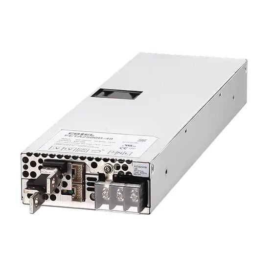
1 Terminal Blocks
5
4
FETA
0
9
1AC (L) Input Terminals AC170 - 264V 1f47 - 63Hz
2AC (N) (M4)
3Frame ground (M4
)
4+Output
5 -Output
6Output voltage adjustable potentiometer
7CN1
Connectors
8CN2
9LED for output voltage confi rmation (DC_OK)
0LED for fault condition detection (ALARM)
Table 1.1 Pin Confi guration and Functions of CN1, CN2
Pin No.
Pin Name
1
AUXG
2
AUX
3
WRNG
4
WRN
5
PGG
6
PG
7
RCG
8
RC
9
COM
10
TRM
11
VB
12
CB
Table 1.2 Matching connectors and terminals on CN1, CN2
Connector
CN1
S12B-PUDSS-1 PUDP-12V-S
CN2
CN1
CN2
Fig.1.1 Connector pin numbers
FETA-6
AC-DC Power Supplies Enclosed type
3
2
1
8
7
6
Function
Auxiliary power output (GND)
Auxiliary power output
Warning signal (GND)
Warning signal
Alarm signal (GND)
Alarm signal
Remote ON/OFF (GND)
Remote ON/OFF
Signal ground
Adjustment of output voltage
Voltage Balance
Current Balance
Housing
Terminal
Reel : SPUD-001T-P0.5
or SPUD-002T-P0.5
11
12
1
2
11
12
1
2
2 Functions
2.1 Input Voltage Range
¡ Input voltage range of the power supplies is from AC170V to
AC264V.
¡ In cases that conform with safety standard, input voltage range is
AC200-AC240V (50/60Hz).
¡ If input value doesn't fall within above range, a unit may not oper-
ate in accordance with specifi cations and/or start hunting or fail.
If you need to apply a square waveform input voltage, which is
commonly used in UPS and inverters, please contact us.
¡ When the input voltage changes suddenly, the output voltage ac-
curacy might exceed the specifi cation. Please contact us.
2.2 Inrush Current Limiting
¡ An inrush current limiting circuit is built-in.
¡ If you need to use a switch on the input side, please select one
that can withstand an input inrush current.
¡ Relay technique is used in the inrush current limiting circuit. When
you turn the power ON/OFF repeatedly within a short period of
time, please have enough intervals so that the inrush current limit-
ing circuit becomes operative.
¡ When the switch of the input is turned on, the primary inrush cur-
rent and secondary inrush current will be generated because the
relay technique is used for the inrush current limiting circuit.
2.3 Overcurrent Protection
¡ An overcurrent protection circuit is built-in and activated at 105%
- 120% of the rated current. A unit automatically recovers when a
fault condition is removed.
Please do not use a unit in short circuit and/or under an overcur-
rent condition.
¡ Low-voltage protection is activated when output voltage is re-
duced by over current protection under the low-voltage protection
value.
Mfr.
2.4 Overvoltage Protection
J.S.T
¡ An overvoltage protection circuit is built-in. If the overvoltage pro-
tection circuit is activated, shut down the input voltage, wait 10 or
more seconds and turn on the AC input again to recover the out-
put voltage.
Note :
¡ Please avoid applying a voltage exceeding the rated voltage to an
output terminal. Doing so may cause a power supply to malfunc-
tion or fail. If you cannot avoid doing so, for example, if you need
to operate a motor, etc., please install an external diode on the
output terminal to protect the unit.
2.5 Low-voltage Protection
¡ Low-voltage protection is built-in. This protection will shut down
the output with the activation. To restart the output, recycle AC
input after 10 or more seconds.
Instruction Manual